Increase IoT Communication Range with Front-End Modules
What you’ll learn:
- How link budget determines the range of wireless connections.
- How front-end modules (FEMs) are architected.
- How FEMs improve both transmit power and receive sensitivity.
- How FEMs enable radio coexistence, increase range, and extend battery life.

The number of connected devices in homes, factories, and cities is increasing year over year. According to ABI Research, IoT products such as smart doorbells, security cameras, water sensors, and asset trackers are expected to grow at double-digit annual rates through 2028 (Fig. 1).
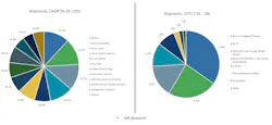
This growth covers a wide range of wireless standards and applications, each with its own modulation and coding schemes, frequency spectrum, and current consumption requirements. Personal-area-network protocols such as Bluetooth Classic and Bluetooth Low Energy (BLE) reside at the low-range, low-data rate end while wide-area protocols such as 5G and LTE sit at the other end, covering kilometers of range at gigabit speeds.
In between, low-power LAN/WAN protocols such as Zigbee, Thread, Matter, LoRa, Z-Wave, and NB-IoT target medium-long range applications with lower data rates and extremely low power (Fig. 2).
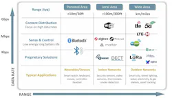
As data rates elevate, power consumption increases accordingly, limiting the applicability of some of these protocols in compact battery-operated devices. In addition, some frequency bands are licensed to network operators, which have exclusive use of that spectrum. As a result, most IoT devices tend to operate in the unlicensed sub-1-GHz ISM bands at 434 MHz, 868 MHz, and 900 MHz, and in the 2.4-GHz band.
Main Drivers in IoT Applications
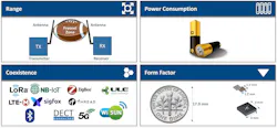
Four key requirements are increasingly driving modern IoT designs:
- Range: Reliably transmitting data over longer distances.
- Power consumption: Operating on a small battery as long as possible.
- Coexistence: Maintaining link reliability in crowded frequency bands.
- Form factor: Integrating these features into ever-smaller devices. A front-end module (FEM) is one of the few RF devices capable of simultaneously addressing all of these constraints (Fig. 3).
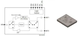
FEMs support multiple operating states: transmit, receive, bypass, or sleep, each controlled via GPIO signals typically driven directly by the host SoC/MCU. They are available for every wireless standard, frequency band, power level, and form factor, enabling designers to select a device that meets the system requirements without design trade-offs.
Wireless Link Range Fundamentals
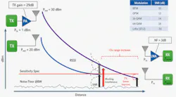
The maximum usable range of any RF link is determined by its link budget, which can be represented as:
PRX = PTX + GTX – LPL + GRX
where PRX is the received power, PTX is transmit power, GTX and GRX are the antenna gains at each end, and LPL is the path loss. As the distance increases, path loss grows accordingly until the received signal goes below the receiver sensitivity threshold, leading to errors and link failure (Fig. 5).
There are three primary ways to extend range:
- Increasing transmit power: A more powerful PA boosts the transmitted signal, increasing the PTX term in the above equation. Similarly, a better transmit antenna (higher GTX) improves range by boosting the radiated power.
- Improving receiver sensitivity, defined as the minimum signal level needed above the local noise floor for reliable demodulation: Receiver noise figure is the primary parameter designers can optimize. In addition, a higher gain (GRX) receive antenna improves range by increasing the received signal level.
- Reducing propagation losses and interference between transmitter and receiver: While free-space conditions yield the longest range, obstacles, absorption, blockers, and multipath effects can introduce significant attenuation and receiver desensitization, both of which increase the LPL term and reduce the available link budget.
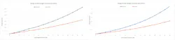
The performance gains from improving any of these parameters are significant. Range simulation at 915 MHz and 2.4 GHz across outdoor and indoor office environments demonstrates that each incremental dB of link budget produces a larger increase in range (Fig. 6).

This becomes even more apparent when you plot the range multiplication factor vs. link budget increase (Fig. 7). This is the underlying reason why an FEM’s extra decibels of gain or sensitivity can translate into significant improvements in real-world coverage.
Boosting the Transmit Side
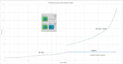
The primary advantage of a FEM is its ability to transmit at power levels well above what the SoC's integrated PA can typically deliver. For example, most BLE SoCs are rated for +8 to +10 dBm of output power, even though the BLE specification and regulatory limits allow up to +20 dBm. Similarly, most 802.15.4 SoCs (Zigbee, Thread, Matter) can deliver around +10 dBm of output power while regulatory limits allow +20 dBm or more.
In all these applications, adding a FEM can close this 10-12 dBm gap and increase the transmit power to over +20 dBm (Fig. 8), while still complying with regional regulatory requirements.
Reducing Current Consumption
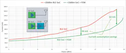
How about the case where the RF SoC integrated PA can deliver +20 dBm without an external FEM? The answer to this question becomes obvious when one analyzes the current consumption of the FEM versus the SoC’s integrated PA at identical transmit power levels.
Measurements comparing a standalone high-power BLE SoC (+20 dBm) against the same BLE SoC's lower transmit power variant (+10 dBm) paired with a FEM show that, at equal output power, the FEM-based solution draws less current: 28 mA less at +15 dBm and 62 mA less at +20 dBm (Fig. 9). Due to its higher power-added efficiency (PAE) of approximately 39% vs. about 22% for the integrated PA, the FEM can simultaneously increase range and reduce the overall system current consumption.
Improving the Receive Side
The FEM can bring benefits on the receive side as well. Receiver sensitivity follows the standard formula:
Sensitivity = −174 dBm/Hz + NF + 10log(BW) + SNR(dB)
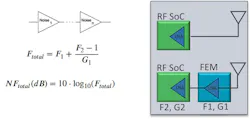
where bandwidth (BW) and required signal-to-noise ratio (SNR) are determined by the wireless standard, leaving only noise figure as the primary parameter an RF engineer can optimize. The impact of a FEM on sensitivity can be analyzed using cascaded amplifier theory. For two cascaded gain stages, the Friis noise factor equation shows that the first amplifier in the chain dominates the total noise figure (Fig. 10). Therefore, placing the low-noise FEM’s LNA ahead of the SoC reduces the overall system noise figure, improving sensitivity and extending range.
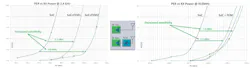
Measured packet-error-rate (PER) results confirm the sensitivity improvements predicted by the theoretical analysis. At 2.4 GHz, combining a BLE SoC with a FEM yields 2 to 4 dB of sensitivity improvement, depending on the FEM evaluated. This is consistent with typical FEM noise figures of 2 to 4 dB compared with the SoC’s embedded LNA of about 6 to 7 dB.
At sub-1-GHz frequencies, the improvement is smaller — 1.5 to 1.8 dB at 915 MHz — but the underlying mechanism is the same: Adding a FEM with a lower noise figure in front of the SoC's internal LNA improves overall system sensitivity (Fig. 11).
Coexistence Mitigation
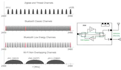
In real-world deployments, wireless range is often limited by interference rather than sensitivity alone. This is particularly true in multi-protocol gateways operating in the crowded 2.4-GHz band, where Wi-Fi, Zigbee/802.15.4, and BLE radios operate in proximity. A Wi-Fi radio can generate a +20-dBm interferer overlapping BLE or Zigbee channels.
Because the protocols operate asynchronously, BLE or Zigbee receivers can’t simply suspend operation during a high-power Wi-Fi transmission. This leaves the front-end susceptible to desensitization or saturation.
Two layers of mitigation are effective. At the system level, channel management and packet traffic arbitration (PTA) are techniques employed in collocated multi-radio platforms. These mechanisms enable radios to operate on non-overlapping channels or coordinate airtime, thereby avoiding mutual interference.
At the FEM level, additional options include operating the LNA in bypass mode to avoid desensitization. The LNA bypass path delivers more than 10 dB of small-signal gain reduction with a switching time under 400 ns, fast enough to protect the receive chain the moment a blocker is detected.
Antenna diversity can also be employed to exploit spatial variation in interferer strength. In addition, antenna diversity can be a highly effective technique in mitigating multipath fading. Due to phase differences, the signals incident on two properly spaced diversity antennas can have a null at only one of them but not on both, hence preserving link robustness (Fig. 12).
FEM Form Factor
FEMs are highly integrated and come in packages as small as 1.2 × 1.7 mm. They require only a minimal number of external components, resulting in negligible PCB space. Thus, they’re well-suited for compact IoT devices.
Often, industrial design and mechanical constraints force engineers into sub-optimal, lower-gain antenna designs. FEMs can help offset the performance penalty associated with smaller antennas, giving designers the freedom to meet the mechanical constraints without sacrificing wireless performance.
Case Study: 2.4-GHz Gateway
A gateway use case illustrates the combined transmit and receive side benefits of adding a FEM. The example demonstrates how FEMs provide design flexibility by using the additional link-budget margin either to extend battery life while maintaining range or to increase range while maintaining battery life.
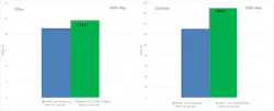
In a baseline configuration with a +10-dBm BLE SoC gateway and a +6-dBm BLE SoC node, measured office/outdoor ranges were 22 m and 131 m, respectively. The battery life on the node advertising at 1 Hz was estimated at 1,000 days.
Adding a FEM to the gateway SoC improves system sensitivity, allowing the BLE node to reduce transmit power to +2 dBm (maintaining the same range), yielding a 14% battery-life extension (1,139 days). Similarly, with a +20-dBm SoC gateway and +20-dBm SoC node, using the lower-power (+10 dBm) SoC variant and adding a FEM at both ends of the link results in a 176% increase in node battery life while maintaining the same range of 32 m office / 331 m outdoor (Fig. 13).
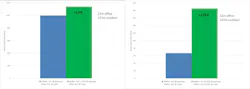
Alternatively, when using the same baseline configuration as above but now optimizing for range, adding the FEM at the gateway can increase the range from 22 m office / 131 m outdoor to 25 m office / 171 m outdoor — an increase of 11% and 30% while maintaining the same battery life at the node (Fig. 14).
FEMs have become a key building block in modern IoT designs. By simultaneously increasing transmit power, improving receiver sensitivity, mitigating interference, and reducing system power consumption, FEMs provide additional link-budget margin, enabling engineers to optimize tradeoffs across RF performance, power, and size.
As IoT deployments continue to expand, FEMs offer engineers one of the most effective ways to improve wireless performance without redesigning the underlying radio architecture.
References:
ABI Research, IoT device shipment forecast, 2024–2028 (cited by Skyworks Solutions).
Silicon Labs, RF Range Calculator.
>>Download the PDF of this article
 dreamstime__everythingpossible_159515701
About the Author
 Marius Turculet
Technical Director, Field Applications Engineering, Skyworks Solutions
Marius Turculet is a Technical Director, Field Applications Engineering, for Skyworks Solutions, where he supports customers developing technical solutions for automotive, consumer, and industrial markets.
Related
dreamstime__everythingpossible_159515701

 Leaders Logo
Leaders relevant to this article: