Wi-Fi 7 Certification: What RF Test Automation Must Actually Validate
What you'll learn:
- Why Wi-Fi 7's 320-MHz channels and Multi-Link Operation multiply the RF test matrix instead of just extending it.
- Which compliance gates (spectral masks, EIRP/TRP, DFS, AFC) apply across the 2.4/5/6-GHz bands and why they vary by region.
- Why channel puncturing and concurrent multi-link states break traditional sequential test scripts.
- What a test architecture built for MLO-era RF validation really looks like.

Wi-Fi 7 didn't just add another checkbox to the Wi-Fi Alliance's certification suite — it rewrote the RF test matrix underneath it. Between 320-MHz channels, Multi-Link Operation (MLO), and 4K QAM, the standard introduces enough new simultaneous RF states whereby a certification process built around sequential, single-band test scripts starts to break down.
For RF and validation engineers, the practical question isn't whether a device conforms to Wi-Fi 7's spec sheet on paper. It's whether the test architecture behind it can truly exercise every state that spec sheet implies before a device ever reaches a formal test lab.
What Wi-Fi 7 Changes at the RF Layer
Most of the increased complexity is due to three architectural changes:
- 320-MHz channels double the widest channels currently available in Wi-Fi 6, and as a result, the multi-gigabit speeds Wi-Fi 7 is built upon will be available anywhere regulators open the 6-GHz band.
- MLO can allow a device to transmit and receive data at the same time on multiple links, possibly over the 2.4-, 5-, and 6-GHz bands simultaneously, to provide more capacity, less latency, and increased link reliability.
- With 4K QAM, transmission rates are about 20% higher than 1024 QAM, the modulation maximum of Wi-Fi 6.
This is on top of an already considerable base level. On its own, Wi-Fi 6 introduces 12 modulation and coding schemes (MCS 0-11), channel widths ranging from 20 to 160 MHz, and guard interval configurations that vary throughput by approximately 10%.
Wi-Fi 7 doesn't replace that baseline. It stacks wider channels, concurrent multi-band links, and a higher modulation ceiling on top of it (Fig. 1). The result is a test surface that grows by multiplication, not by increments, since every extra link, channel width, and modulation state can combine with every other one.
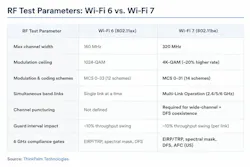
MLO alone comes in more than one flavor, and each has different test implications. In simultaneous transmit and receive (STAR) mode, a device's links work independently and asynchronously, with each maintaining its own channel access parameters. In non-simultaneous transmit and receive (NSTR) mode, transmissions across links must be synchronized, and at any given moment all active links can only send or only receive, never both at once. A test plan that only validates STAR behavior and assumes NSTR devices will behave the same way is validating the easier case and skipping the one more likely to fail in the field.
The Compliance Gates that Can't Be Skipped
None of this changes the underlying regulatory checklist. It just makes each item harder to clear. RF compliance testing still comes down to bandwidth limits, spectral masks, radiated power (EIRP/TRP), and spurious emissions, and all four vary by region and frequency band. Devices operating in the 5- and 6-GHz portions of the spectrum also must clear dynamic frequency selection (DFS) verification, confirming the device correctly detects and avoids radar signals.
These gates aren't uniform across markets, which is where many test plans fall short. The FCC's standard power class requires AFC coordination and allows for higher transmit power both indoors and outdoors. And ETSI's 6-GHz framework has no standard power category at all, instead relying on low-power indoors and very-low-power classes.
A device engineered around FCC standard power assumptions doesn't automatically map onto ETSI's rules, and a single test plan built for one region can miss what the other requires.
Antenna performance adds a constraint that's easy to underweight until it fails late. A design must hold stable efficiency across the full range of 2.4 to 7.125 GHz. That’s because instability anywhere in that span raises the risk of failure specifically during high bandwidth or MLO testing, when multiple bands are active and interacting at once instead of being measured in isolation.
Why MLO and Puncturing Break Linear Test Scripts
Most legacy test scripts were written around a simple assumption: Test one band, one channel width, one modulation state at a time, then move to the next. MLO breaks that assumption at the architecture level. A device negotiating simultaneous links across 2.4, 5, and 6 GHz must be validated in combined states, covering link establishment, load balancing across links, and failover behavior when one link degrades, not just in each band's isolated performance.
Channel puncturing makes this even harder. A device may need to punch out a portion of a wide channel to avoid a DFS-restricted segment. Therefore, the test matrix must cover full-width channel performance and every plausible puncturing pattern, combined with every MLO link state that might be active at the same time. A manual or sequential script approach that worked fine for a single-band Wi-Fi 6 device doesn't scale to a matrix with this many concurrent variables.
It's not that the individual tests are harder. There are simply too many valid combinations to walk through one at a time within a realistic development schedule.
With MLO, the test is not only different, but it’s even altered. Legacy single-band roaming is “reactive” in that the client must detect the degradation, scan, and re-associate overall for a period of typically 100 to 300 ms, which is long enough to drop a VoIP link or stall a video circulation. Instead, with MLO-capable clients, traffic can be shifted to an already-associated secondary link within a few milliseconds, without performing a full reassociation.
Validating such behavior involves confirming that the sub-millisecond failover really works under real degradation and real puncturing — not just under the reassociation-based roaming tests designed for single-band devices.
What a Test Architecture Built for This Looks Like
The practical response is to separate test intent from device control and RF lab infrastructure, so combinations can be generated and executed programmatically instead of scripted one by one (Fig. 2).
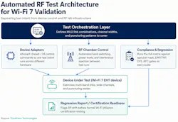
An orchestration layer defines which MLO link combinations, channel widths, and puncturing patterns need coverage. Device adapters abstract the actual control commands across chipsets and operating systems, so the same test intent runs against different hardware without a rewrite. RF chamber control automates band switching, power level changes, and interference injections, replacing manual chamber reconfiguration between test runs.
Traceability matters as much as coverage here. Every test run needs to log which combination of link state, channel width, and puncturing pattern was active when a failure occurred, because a result that just says “MLO test failed” gives an engineer nothing to act on.
A properly instrumented pipeline ties each result back to the exact RF state under test. It turns a regression report into something a design team can debug against instead of just a pass/fail count.
The payoff shows up on the regression side. Every firmware build can run back through the same matrix automatically. That’s what catches RF drift, like a beamforming change quietly narrowing a device's effective coverage, or a puncturing update breaking a DFS fallback path, while it's still cheap to fix rather than after it surfaces during formal certification testing.
Building this in-house isn't always the right call. The orchestration layer, device adapters, and chamber automation described above represent a meaningful engineering investment on their own, separate from the product being certified. Many hardware teams instead work with a dedicated wireless testing partner to create and maintain that infrastructure, rather than building and staffing it from scratch for a single product line.
The Takeaway for RF and Test Engineers
Wi-Fi 7 certification isn't failing devices because the compliance requirements are new. EIRP limits, spectral masks, and DFS behavior are well established. It's failing devices whose test process wasn't built to exercise the combined RF states created by MLO and wide channels. Teams that rebuild their test architecture around concurrent multi-band validation, instead of just bolting more test cases onto a single band script, are the ones clearing certification without late-stage surprises.
>>Download the PDF of this article
 dreamstime__pongsak_ray_310874325
About the Author
Midhula Mariyam Jeevan
Technical Contributor, ThinkPalm Technologies
Midhula Mariyam Jeevan, technical contributor, researches and writes on wireless connectivity and Wi-Fi technology at ThinkPalm Technologies. Her work has covered emerging standards including Wi-Fi 6E and Wi-Fi 7, RF test automation, and IoT wireless validation. Midhula has led content strategy and performance analysis for the company's technical blog, using search and engagement data to guide coverage of wireless and networking topics.