5G Synchronization for Cost-Sensitive Cable Modems

Members can download this article in PDF format.
What you’ll learn:
- New specifications for mobile backhaul over the cable network that can address the performance requirements of 5G RAN.
- How next-generation, low-cost silicon timing can convert from DOCSIS Timing Protocol (DTP) to both IEEE 1588 and Synchronous Ethernet clocks used for eCPRI fronthaul timing.
- Key features to look for in new timing silicon to operate as a synchronous network equipment master clock.
5G radio access networks (RANs) require a new approach to designing and building networks. Work by organizations like CableLabs is spawning specifications for mobile backhaul over the cable network that can address the performance requirements of 4G/LTE and 5G RAN.
The existing Data Over Cable Service Interface Specification (DOCSIS) hybrid fiber coax (HFC) infrastructure provides many advantages for wireless backhaul. For example, a North American operator case study found that all of the ideal small-cell locations were within 10 meters of coax.
DOCSIS transport itself is synchronous in nature and uses a common clock derived by the cable-modem termination system (CMTS). This clock has a ±5-ppm clock accuracy.
DOCSIS 3.1 introduced the DOCSIS Timing Protocol (DTP) to measure the asymmetries in the HFC network and provide an adjustment factor to the DOCSIS timestamp. It allowed for much more precise time distribution over the HFC, including synchronizing the DOCSIS domain to a network source, such as a Primary Reference Time Clock (PRTC).
Mobile Backhaul
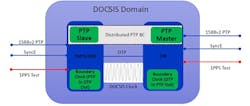
A CableLabs committee made up of industry experts recently looked at mobile backhaul over DOCSIS. The committee saw the need for 4G/5G synchronization within the cable modem (CM). Figure 1 shows the new DOCSIS 3.1 domain providing mobile-backhaul synchronization. Mobile backhaul refers to the network providing connectivity between the mobile switching core (or what’s also known as the evolved packet core [EPC] for LTE, or next-generation core [NGC] for 5G) and the RAN node.
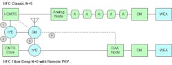
DOCSIS 3.1 introduced a new modular headend architecture (MHAv2) that required a remote DOCSIS timing interface (R-DTI) through the converged interconnect network (CIN). CableLabs also is working to define R-DTI.
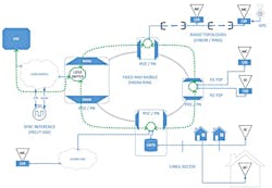
If the DOCSIS network is providing the backhaul service, it now needs to be part of the timing distribution chain, carrying precision timing down to the CM and into the Wireless End Application (WEA) network. The DOCSIS Timing Protocol (DTP) was designed to carry this precise timing, enabling the DOCSIS link to work with other elements of the operator’s network to meet the overall timing requirement needed by the radio base-station slave clock. Figure 2 shows an example deployment scenario of the current mobile backhaul.
The primary focus of the present release of the DOCSIS synchronization techniques specification (CM-SP-SYNC) is on the mobile backhaul (MBH) application. A MBH network connects the mobile switching core (EPC or NGC) and the RAN node. The CM-SP-SYNC document looks at using DOCSIS technology to carry precision frequency and/or phase synchronization signals; with the hybrid fiber-coax (HFC) plant as a segment of an operator’s overall timing-distribution chain.
Traditional mobile base stations need to be frequency-synchronized to establish proper frequency alignment, which guarantees certain network key performance indicators (KPIs) such as successful call establishment and handover. In addition to frequency synchronization, LTE TDD and the latest generations of mobile technologies such as LTE-A, which include coordinated multipoint (CoMP) and enhanced inter-cell interference coordination (eICIC), all require stringent time and phase synchronization.
Supporting such features places additional synchronization requirements on the mobile backhaul network. Because this article focuses more on the CM as a synchronous network equipment master clock, we will not go into the details of these synchronization requirements. Instead, please refer to CM-SP-SYNC Appendix III for a technical overview.
Reference System and CM-SP-SYNC
To provide MHB service over the DOCSIS network and the HFC plant, we must first look at a reference system. Figure 3 is taken from CM-SP-SYNC and shows the reference system’s connectivity to GNSS. For 4G/LTE and 5G mobile services, the maximum time error (max|TE|), which includes all time-error sources, has a target of 1,500 ns. The time-error budgets comprise multiple components:
- Constant time error (cTE): Error that doesn’t change in steady state.
- Dynamic time error (dTE): Error that does change in steady state (per ITU-T G.8273.2, fast changes are >0.1 Hz and slow changes are <0.1 Hz).
- Rearrangement: Abrupt changes caused by network reconfiguration.
- Holdover: Long-term stability in case of reference source failure.
The CM-SP-SYNC specification allows for the cable operator to mix and match different classes of equipment, different numbers of Ethernet switch hops, and different DOCSIS network architectures to arrive at its own network design—if the overall target is maintained at the mobile base stations. To help, CM-SP-SYNC splits the DOCSIS reference system into three distinct network segments and allocates a time-error budget to each network segment. The remainder of this article focuses on the WEA network, from the CM to CPE interface (CMCI) port to the WEA air interface.
Wireless End Applications
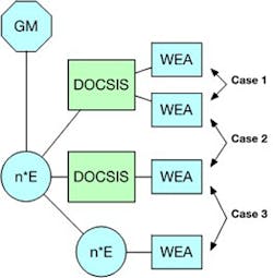
There are three cases of how WEAs are related through the DOCSIS network (Fig. 4). The “E” in Figure 4 represents an Ethernet switch, which can be a participant node (a boundary clock, or BC) or a non-participant node.
- Case 1: Two WEAs, typically two small cells, connected to the same DOCSIS network. Time error is contained within a single DOCSIS network.
- Case 2: Two WEAs, typically two small cells, connected to different DOCSIS networks. Time error is distributed across two DOCSIS networks and an IP network segment.
- Case 3: A WEA connected to a DOCSIS network that’s communicating with a macrocell WEA on a separate IP network segment. Time error is distributed across a DOCSIS network and an IP network segment.
For mobile backhaul, the CM provides phase and frequency synchronization services upstream to the WEAs. From the WEA’s perspective, the CM is a synchronous network equipment master clock. However, the CM is a “dumb” node in the DOCSIS network and always works in conjunction with the CMTS, including deriving its DOCSIS timestamp from DTP.
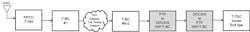
For this reason, we must look at the DOCSIS equipment as an Inter-Working Function (IWF) used to convert PTP and SyncE to the DOCSIS protocol (running on the I-CMTS, RPD, or RMD), and as a second IWF used to convert the DOCSIS protocol (running on the CM) back to PTP and SyncE. Figure 5 shows a generic example deployment scenario with DOCSIS equipment.
The ITU-T coined the term IWF to describe synchronization network segments that are running different PTP profiles (see ITU-T G.8285 Appendix III). However, it also can be used to describe the DOCSIS network segments running both PTP and DTP. IWF is used throughout CM-SP-SYNC to describe the DOCSIS network segments, including for the CM that’s performing the DOCSIS-to-PTP IWF/T-BC.
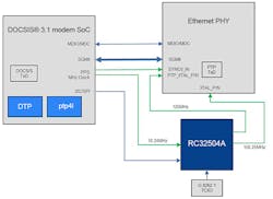
The intention of the IWF is to faithfully replicate the functionality of [G.8275.1] from a PTP profile point of view. That includes the operation of the Best Master Clock Algorithm (BMCA), the transfer of all PTP fields (such as those in the Announce messages), and other information. This IWF model approach is used for the DOCSIS network. Figure 6 shows an example component-level block diagram for the CM performing the DOCSIS-to-PTP IWF/T-BC.
As a synchronous network equipment master clock, the CM must provide two clocks:
- A frequency clock over the physical layer, per ITU-T G.8262 Synchronous Ethernet Equipment Clock (EEC, or SyncE); and
- A phase/time clock over the packet layer, per ITU-T G.8273.2 Telecom Boundary Clock (T-BC). This includes running two protocols: 1) ESMC (ITU-T G.8264); and 2) PTP (following the port state protocol as defined in IEEE 1588-2008). The protocols are out of the scope of this article.
Counting on the Clocks
Looking at the network clocks, the CM alone doesn’t provide the clock performance. You must look at the DOCSIS system as a two-box system. In other words, the total DOCSIS synchronization portion of the chain should meet the performance requirements when measured in isolation, between the PTP input on the first IWF (PTP-to-DOCSIS) and the PTP output on the second IWF (DOCSIS-to-PTP).
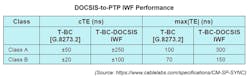
The performance requirement is covered in ITU-T G.8273.2, Appendix V, “Performance Estimation for Cascaded Media Converters acting as T-BCs.” However, the CM time error isn’t specified to fully follow [G.8273.2]. The CM must comply with only the following max|TE| and cTE requirements shown in the table, excluding DTP.
The resulting DOCSIS timestamp will generate a counter that increments at a rate of 10.24 MHz for a period of approximately 97.66 ns. This will need to be converted to a PTP timestamp, which is a counter that increments at a rate of 1 GHz for a period of 1 ns. Some CM may provide a finer time resolution for the DOCSIS timestamp using an increment at a rate of 20 × 10.24 MHz, or 204.8 MHz, for a period of approximately 4.88 ns.
Either way, a synthesized clock representing the DOCSIS timestamp (i.e., 10.24 MHz or 204.8 MHz) can be locked to by a silicon phase-locked loop (PLL) to rate-convert to an Ethernet physical-layer reference clock and PTP timestamp counter clock. Because both timestamps are based on International Atomic Time (TAI) starting 00:00:00 January 1, 1970, no starting offset is required, and a simple 1 pulse-per-second (1-PPS) trigger can be used to synchronize the time of day (ToD) between the two timestamp counters. This is because the PLL takes care of the rate conversion (with 0 PPM translation error, so no need to worry about remainder of a division operation).
Because DTP is unidirectional for timing, it only makes sense for the CM to act as a synchronous network equipment master clock. This means the CM will look like the SyncE master for physical-layer timing and as the PTP GrandMaster (GM) for packet-base timing.
To improve the filtering of the clock for use as a master clock, it’s recommended to use a temperature-compensated crystal oscillator (TCXO) for the CM’s local clock source (both for the physical layer and the PTP timestamp counter). This would allow for filtering of the DOCSIS symbol clock using bandwidths below 10 Hz. It also will enable the CM to provide frequency holdover capability upstream on the loss of DTP.
However, most WEA equipment will have its own holdover capability or maintain alternate sources for time, allowing for a more cost-sensitive solution without a TCXO. In this case, a simple crystal (XTAL) can be used or even silicon clock attenuator with an integrated XTAL.
Off-the-shelf simple frequency-converting clock synchronizers that meet traditional telecom filtering requirements as defined by the ITU-T are becoming more readily available. As the RAN moves toward a more open architecture, it also means the transport of the backhaul or even fronthaul networks could go over non-traditional telecom networks, such as cable. This requires these networks to now service timing-related capabilities without disrupting their existing core services.
CableLabs has already defined mobile-backhaul requirements over the cable network. Now, cable-modem equipment manufacturers can address timing by using these new clock synchronizers and meet the performance requirements of 4G/LTE and 5G RANs.
About the Author
Greg Armstrong
Principal Engineer – System Design, Renesas Electronics
Greg Armstrong has worked in the telecommunications industry for 27 years and focusing on synchronization for the last 17 years. Greg’s expertise is in technologies that enable the transfer of frequency, phase, and time synchronization over packet networks (SyncE, IEEE 1588, NTP, ToP, RTP, and CESoPSN). As a Principal System Architect at Renesas Electronics (which acquired Integrated Device Technology in 2019), he’s responsible for the technical definition of new timing products (both silicon and software) around network synchronization.
Greg has presented papers at various conferences and, since 2016, he’s been providing a tutorial on phase-locked loops (PLLs) at both ITSF and WSTS. He also represents Renesas in the IEEE 1588 working group and was a key contributor to the CableLabs Synchronization Techniques for DOCSIS® Technology Specification for Mobile Backhaul.
Greg started his career at Bell Northern Research (Nortel Networks) in Ottawa, Canada. He previously held the position of Senior Application Engineer at Microsemi (who acquired Zarlink Semiconductor in 2011). He holds a Bachelor of Applied Science in Electronic Systems Engineering from the University of Regina, Canada (1995).
