GaN-on-SiC MMIC PAs Meet 5G Network and Commercial Space System Needs

Members can download this article in PDF format.
What you’ll learn:
- Nonlinear behavior is a growing concern in higher-order satcom modulation schemes.
- GaN can extend 5G NR femtocell and picocell base-station deployments into the mmWave band.
- SiC-based substrates boost power density by improving thermal conductivity for MMICs.
RF power amplifiers (PAs) are under pressure to perform as never before in a growing variety of applications. The technology is being called upon to support higher gain targets without adding cost, size, weight, or complexity. They’re also expected to deliver the necessary linearity and efficiency to accommodate higher-order modulation schemes that are even more sensitive to distortion than their predecessors. Board space is at a premium, but until now the path to more compact solutions faced difficult peak-to-average power ratio (PAPR) tradeoffs.
These challenges are being solved with a new generation of gallium-nitride (GaN) monolithic microwave integrated-circuit (MMIC) PAs that are seeing greater adoption where they’re needed most. With proper implementation, designers can maximize the value of these devices in applications ranging from space- and ground-based commercial and defense satellite communications to test equipment.
Expectations are particularly high for this technology’s use in 5G networks, none more so than in the unused millimeter-wave (mmWave) band that carriers are embracing for the most congested portions of their subscriber base.
New Era with New Needs
In the aerospace and defense sector, a rapidly evolving commercial space market is experiencing its most dramatic changes in decades. A similar set of conditions are driving the 5G mobile communications industry, where growing data congestion in densely populated urban areas poses an extremely difficult challenge.
For these and other applications, systems rely on high-performance power technology to meet the high-speed data rates required for video and broadband data. New power solutions are needed, including high-performance RF PAs that can juggle conflicting requirements to improve performance across the entire transmission path.
For example, PAs must be able to operate in their linear region where distortion products are minimal. At the same time, though, because less RF output power can be delivered in this region, more gain stages are needed to achieve the required gain, adding complexity, cost, size, and weight.
Further complicating matters, if the PA is operated beyond or even near its saturation point to maximize conversion efficiency and generate as much power as possible, digital predistortion or other techniques must be used to compensate for the inevitable AM-AM and AM-PM distortion.
AM-AM distortion is a reference to gain distortion, or the compression or peaking of the PA with input power, which often occurs due to device nonlinearities. AM-PM distortion describes the output phase variation against input power, which is often caused by the PA’s nonlinear capacitors.
Another hurdle is that the higher-order modulation schemes used in satellite communications, such as 64/128/256 quadrature amplitude modulation (QAM), are extremely sensitive to nonlinear behavior. The signal’s state is difficult to determine as it “moves” around the constellation.
The inner states may not be distorted because they require less power. The outer ones, though, are a different story. Distortion occurs when the amplifier is driven into compression. Ideally, a modulation scheme for satellite transmission would have higher spectral efficiency than quadrature phase-shift keying (QPSK) but be more resistant to distortion than QAM. Amplitude phase-shift keying (APSK) is increasingly used because it has the best of both worlds and lends itself well to predistortion.
Also challenging is how to achieve the necessary PAPR, which is the ratio of the highest power the amplifier will produce to its average power. PAPR is important because the amount of data that can be sent is proportional to the average power, but the size of the amplifier needed for a given format depends on the peak power. These represent just a few of the conflicting challenges that have confounded designers prior to the arrival of GaN MMIC PAs, especially in satellite and 5G applications.
Solving Ka-band Satcom Challenges
NASA created a host of new opportunities for space-launch companies and satellite operators when it enabled the private sector to populate space with low-Earth-orbit (LEO) satellites. Thousands of these satellites now circle the globe, delivering services ranging from broadband internet access to navigation, maritime surveillance, and remote sensing.
Most of these satellites operate in the Ka-band’s spectrum of 27.5 to 31 GHz, which is more than 4X that of lower-frequency allocations. This frequency band is playing a major role in supporting the tsunami of traffic being generated by video and other data-intensive applications and is ideal for GaN MMIC offerings.
GaN offers significant advantages as compared to traveling-wave tubes (TWTs), which have traditionally been used as power sources at these frequencies. TWTs have lower efficiency and require extremely high operating voltages. GaN also is inherently radiation-tolerant—a valuable benefit when the satellite is in a very high geosynchronous orbit.
Much smaller than their TWT-based predecessors, GaN-based amplifiers are better suited for use with active phased-array antennas, too. They eliminate the need for complex and cumbersome power combiners.
As an alternative to gallium-arsenide (GaAs) options, GaN amplifiers deliver more RF power in a smaller footprint and operate at higher voltages. This makes them more efficient than GaAs amplifiers, although the latter are generally preferred for low-power driver stages.
Solving the 5G Network Density Problem
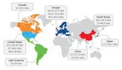
The RF spectrum between 24 and 100 GHz also is ideal for a portion of 5G network activities that’s focused on neighborhood extension using small cells and repeaters. This mmWave frequency spectrum sees very little use as compared to lower-frequency bands struggling to accommodate the growing congestion from signal traffic, including TV, radio, and current 4G LTE networks operating between 800 and 3000 MHz. Figure 1 shows the likely proliferation of frequency bands for 5G mmWave.
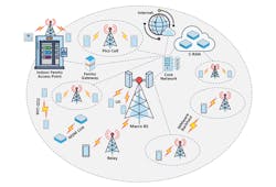
While the lower-frequency bands cover much greater distances, they offer slower data speeds. The higher-frequency bands, on the other hand, cover much smaller areas but can carry significantly more data, which is exactly what 5G carriers need in the densest parts of their networks (Fig. 2).
Carriers can use the mmWave band to increase data bandwidth over smaller, densely populated areas such as stadiums, malls, and convention centers, or anywhere else where data congestion is a problem. For the rest of the coverage area in rural towns and villages, sub-6-GHz solutions and bands below 2 GHz will suffice.
The 5G network consists of macro base stations and small cells. Macro base stations are connected to the core network using the fiber-optic links for mmWave backhaul. They can talk directly to cell phones or to the small cells that talk to the user-equipment mobile device, providing the last-mile connectivity. In addition, picocells and femtocells provide the network connectivity inside office buildings. In these environments, the connection might be weak or there might be high user density.
With output power of less than 1 W, picocells and femtocells improve coverage within a small area. High-density small cells have output power up to 10 W and provide connectivity up to 50 meters. Low-density small cells maintain output power up to 160 W and provide coverage up to 500 meters. Macro base stations have output power up to 480 W and coverage up to 2.5 km.
5G effective isotropic radiated power (EIRP) is mandated by the Federal Communication Commission (FCC) in the U.S. The base-station transmit power limit is 75 dBm/100 MHz, with maximum transportable power of 55-dBm EIRP for a base station and 43-dBm EIRP for a mobile phone. The power amplifier that provides the EIRP levels must meet linearity requirements of 17-dB adjacent-channel leakage ratio (ACLR) and an error-vector magnitude (EVM) requirement based on the modulation scheme (QAM 64 = EVM 8%, QAM 256 = EVM 3%).
GaN can extend 5G New Radio (NR) femtocell and picocell base-station deployments into the mmWave band, where they will have the needed bandwidth along with impressive data rates. Laterally diffused metal-oxide semiconductor (LDMOS) MOSFETs can’t accomplish what’s needed at >3.5 GHz. Nor can GaAs, which can’t deliver high enough power in the mmWave band without moving to an extremely large die.
GaN offers the right combination of higher frequencies and power, wide bandwidth, and the necessary thermal properties, gain, low latency, and high switching speeds. It also offers the higher power efficiency required by 5G NR base station towers so that they can cover both 5G and 4G/3G. But GaN still needs something else.
Benefits of GaN-on-SiC
SiC substrates are pivotal to realizing the promise of GaN technology in these applications. With triple the bandgap of silicon and 2.4X that of GaAs, GaN is better suited to high-power and high-frequency devices. The wider bandgap reduces switching and conduction losses that, in turn, translates to lower size, weight, and total solution costs when powering high-power, high-frequency RF applications.
Using SiC-based substrates takes things a step further, improving power density by enabling MMICs to offer better thermal conductivity as compared to silicon-based wafers. This also improves wafer yields through a better lattice match with GaN, and it reduces package size by 20% as compared to LDMOS technology while improving efficiencies.
Together, these advantages offer critical improvements to size, weight, power, and cost (SWaP-C) for air- and space-based systems. The result: the best combination of high-power density and yield, the smallest footprint and reduced weight, and the highest power support and best efficiency. In addition, it enables high-voltage operation and longevity of more than 1 million hours at a 255ºC junction temperature.
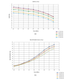
For example, a three-stage MMIC PA using this process technology can achieve 22% power-added efficiency at 10-W saturated output power from 27.5 to 31 GHz when biased at 24 V, and 22-dB small-signal gain (Fig. 3). This type of PA also supports complex modulation, such as 256-QAM, and can reduce power consumption by more than 30% versus alternative GaAs MMICs. Furthermore, such PAs are able to achieve 39-dBm saturated output power from 27.5 to 31 GHz, with 22% power-added efficiency (PAE) and 22-dB small-signal gain.
When evaluating GaN RF PA products, it’s important to make sure that they can be used for linear applications when backed off. On top of that, they should have a balanced architecture that provides excellent broadband input and output match to 50 Ω with return loss of 15 dB across the band.
The inclusion of dc blocking capacitors at the output makes it easier to integrate the PA into the next higher assembly. Also important is the availability of compact models that enable designers to more easily model performance and expedite the design of PAs in their systems.
RF power amplifier options will continue to grow as GaN MMIC PA suppliers extend their offerings across more frequency ranges while also offering bare die, packaged MMIC amplifier products, and complementary offerings like discrete high-electron-mobility transistor (HEMT) devices. These and other products will meet the unique needs of satellite communications networks and 5G NR base stations, including solving linearity and efficiency challenges when using higher-order modulation techniques.
System designers can move beyond GaAs, LDMOS, and TWT-based amplifiers to achieve gain improvements without making cost, size, weight, complexity, or PAPR tradeoffs.
About the Author
Michael Ziehl
Senior Manager, Product Marketing, Microchip Technology
Michael Ziehl is currently Senior Manager, Product Marketing for Microchip’s RF and Microwave products. He has more than 25 years of engineering, marketing, and general management experience in the semiconductor business.
He and his teams have launched many products that opened or expanded new markets; driving design wins, and revenue growth in the mobility (5G), wireless infrastructure, aerospace and defense and industrial market segments. He has authored multiple articles in leading industry publications, and spoken at numerous industry events, panels and webinars.
Prior to joining Microchip, Mike held leadership positions in the RF semiconductor industry at Macom, NXP, and Hittite Microwave. Mike holds an MBA from Rensselaer Polytechnic Institute and a BSEE from Fairfield University.
