Calibration Implementation Techniques for Multichannel Phased-Array Subsystems
What you’ll learn:
- Why calibration is so critical to optimal functionality of multichannel phased arrays.
- The differences between the contrasting approaches to implementing calibration.
- Procedures for validating the cross-correlation calibration method.

Accurate amplitude and phase calibration is essential to achieving the theoretical performance of phased-array antenna systems. Proper calibration applies the correct phase and amplitude weighting to each antenna element. This ensures that desired signals combine constructively (coherently) while noise, being uncorrelated between elements, combines less efficiently (noncoherently).
The result is improved signal-to-noise ratio (SNR) and consistent antenna pattern performance across varying frequencies, temperatures, and operating conditions.
This article focuses specifically on two phase‑alignment techniques used for the evaluation and characterization of the ADXBAND16EBZ X-band phased-array reference design.1 The analysis uses continuous-wave (CW) waveforms and leverages the hardened digital-signal-processing (DSP) blocks of Analog Devices’ AD9084 Apollo mixed-signal front-end device.
The system also utilizes prerequisite multichip synchronization to ensure phase determinism. However, the details of this synchronization process are outside the scope of this article.
Two Phased-Array Calibration Techniques Explained
Calibration on the subsystem platform is essential for ensuring that all 16 transmit and receive channels operate coherently. When the channels align in time, phase, and amplitude, the system achieves the expected coherent combining gain of approximately 24 dB (20 × log10 (16)).
Here, we consider two distinct calibration approaches: the null-power method and the cross‑correlation method. The first is a traditional approach that excels in robustness, while the second is a modern, quicker alternative leveraged as the primary method for characterization.
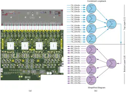
In both cases, we leverage a passive calibration board consisting of a power combiner/splitter and switch network to enable a self-contained transmit-to-receive loopback (Fig. 1). The following sections describe both methods in a detailed, engineering-accurate manner and explain how the system extracts the final transmit and receive phase offsets.
The Null-Power Phased-Array Calibration Method
The null-power method is based on rotating the phase of one channel relative to a reference with fixed phase and observing the superposition magnitude of the two combined channels. The peak magnitude is recorded for each phase step and 180° is added to the phase offset corresponding to the two-channel combined minimum (null) (Fig. 2).
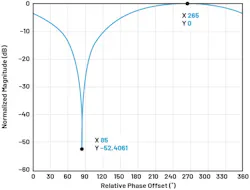
The phase offset is then applied to the numerically controlled oscillator’s (NCO’s) phase shifter of the corresponding channel so that the channel aligns constructively with respect to the selected reference channel. The entire procedure must be repeated for each channel and for each frequency of interest.
Although this approach requires significant time due to its swept nature, it’s extremely robust in noisy or unpredictable environments. It leverages a sinusoidal waveform and doesn’t rely on timing alignment or correlation-based measurements. The main drawbacks are the execution time and the limited information it provides because it yields only phase-offset information.
>>Download the PDF of this article, and check out the TechXchange for similarly themed articles and videos


Additional optimization can be implemented for quicker sweeps using this method. Instead of a fixed phase step, one could start with a coarse step size to find a general range for the null location and use a finer phase-step size to dial in the exact offset for the corresponding null.
The Cross-Correlation Phased-Array Calibration Method
The cross-correlation method is the standard calibration procedure because it aligns phase rapidly and with high precision. The method begins by configuring the calibration board into combined-loopback mode. All transmit and receive NCO phases, including both main and per-channel adjustments, are set to zero so that any measured phase error originates solely from the hardware signal chain.
Next, we generate a pulsed baseband waveform with one pulse assigned to each digital-to-analog converter (DAC) channel in a time-division fashion akin to time-division multiple access (TDMA). These pulses are placed in discrete time slots in a time-interleaved fashion to produce a frame containing 16 non-overlapping pulses once all channels are combined (Fig. 3). We transmit this waveform at the operating RF frequency to serve as the reference for the correlation-based alignment.
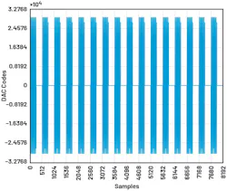
The pulse corresponding to TX_CH<0> has a seven-sequence Barker code, where each sinusoidal period within the pulse envelope of TX_CH<0> has a unique sequence of phase shifts. This helps distinguish the reference channel compared to the other channels by a higher SNR signature in the correlation response. Channels 1 to 15 all have a five-sequence Barker code with its own unique phase-shift sequence. A comparison of TX_CH<0> and TX_CH<1> is shown in Figure 4.
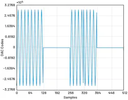
The calibration process starts with each DAC transmitting its respective time-interleaved pulsed waveform and all analog-to-digital converters (ADCs) capturing the 10 data frames of the combined waveform. Each data capture for all 16 ADCs is taken at an arbitrary time, resulting in each data frame shifted by an unknown sample count relative to the others.
Sample misalignment correction is done by selecting an arbitrary data frame as a reference and executing an autocorrelation against all remaining data frames. Each capture is then sample shifted by the appropriate number of samples to achieve alignment based on the autocorrelation sample delay results. Once aligned, the data frames are coherently summed, thus improving the SNR for accurate post-processing (Fig. 5).
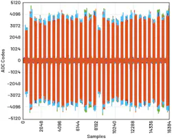
The next step cross-correlates the coherently summed data (Fig. 4, again) and the original transmitted time-interleaved pulse train waveform (Fig. 3, again). The resulting cross-correlation matrix aids in determining the phase offsets relative to a defined reference for all ADCs and DACs. The reference channels TX_CH<0> help identify its location in the time-interleaved pulses and can be used to determine the relative phase offsets of the remaining channels.
The relative difference of the complex angle of the peak correlation response for TX CH<0> across the 16 ADC data frames determines the ADC NCO phase offsets. The relative difference of the complex angle of the peak correlations of TX_CH<15...1> compared to TX_CH<0> within a single ADC data frame determines the DAC NCO phase offsets. In both cases, the phase offsets are phase-wrapped into the range from –180° to +180° to be compliant with the AD9084 device drivers.
Validation of Final Calibration Results
With calibration completed and the derived phase offsets applied, the next step is to validate the effectiveness of the phase-alignment procedure. For a fully coherent 16-element array, the signal power is expected to increase by 20log10 (16), while uncorrelated noise power increases by 10log10 (16).
Figure 6a shows the magnitude of a single transmitted CW waveform digitized by one ADC channel, along with the fast Fourier transform (FFT) of the complex-valued data frame. Figure 6b depicts the combination of all 16 transmitted CW waveforms with the peak magnitude measured from the FFT of a single ADC frame. As expected, the coherent combination yields an approximately 23-dB increase in peak signal magnitude relative to Figure 6a.
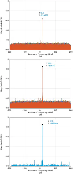
Finally, Figure 6c presents the FFT obtained when all 16 transmit waveforms and all 16 receive channels are coherently summed. In this case, the peak magnitude reaches the average expected level due to bit-growth effects, while the uncorrelated noise combines noncoherently, resulting in an SNR improvement of about 12 dB.
In conclusion, we’ve demonstrated two practical calibration strategies for achieving coherent phase alignment in a 16-by-16 multichannel phased-array subsystem. The null-power method, while time intensive, offers a highly robust means of determining inter-channel phase offsets without reliance on precise timing or correlation metrics. Thus, it’s well-suited for environments with elevated noise or measurement uncertainty.
In contrast, the cross-correlation method provides a rapid and highly accurate calibration approach by exploiting time-interleaved pulsed waveforms, Barker-coded channel identification, and coherent summation of multiple captures to improve SNR and estimation stability.
Measured results confirm that the correlation‑based calibration achieves near-theoretical coherent combining performance, with signal power scaling as expected for a fully aligned 16-element array and noise combining noncoherently across receive channels. The ability to efficiently perform calibration across multiple frequencies enables the generation of high-resolution phase-correction tables suitable for temperature- and frequency-dependent system characterization.
While the current implementation focuses on narrow-band CW excitation, the methodology naturally extends to wideband calibration by leveraging the integrated finite-impulse-response filtering and DSP capabilities of the AD9084. Future work will explore broadband excitation and frequency-dependent calibration to further enhance instantaneous bandwidth performance in large-scale digital beamforming systems.
References
- Siddhartha Das. “Quad-Apollo MxFE: A 16 Receive/16 Transmit X-Band Direct Sampling Digital Beamforming Subsystem Reference Design.” Analog Devices, Inc., January 2026.
- Michael Jones, Travis Collins, and Charles Frick. “Integrated Hardened DSP on DAC/ADC ICs Improves Wideband Multichannel Systems.” Analog Devices, Inc., May 2021.
>>Download the PDF of this article, and check out the TechXchange for similarly themed articles and videos
About the Author
Siddhartha Das
System Applications Engineer, Analog Devices Inc.
Siddhartha Das is a systems applications engineer on the Subsystems and Sensors Team within Analog Devices’ Aerospace, Defense, and Communications Business Unit based in Durham, N.C. He earned his B.S. in electrical engineering from Virginia Tech in 2023 and is currently pursuing his M.S. in electrical engineering from the same institution.
Sam Ringwood
System Applications Engineering Manager, Analog Devices Inc.
Sam Ringwood is a system applications engineering manager for the Aerospace, Defense, and Communications Business Unit located in Greensboro, N.C. Prior to joining Analog Devices, Sam worked in RF test and RF design roles within the U.S. Nuclear Weapons Complex. He received his BSECE degree in 2015 and MSEE degree in 2016 from University of Missouri-Kansas City. Sam is currently focusing on creating subsystem solutions for applications such as phased-array radar.
Related
 Leaders Logo
Leaders relevant to this article: