Evolving Antenna Requirements for LEO and MEO
What you'll learn:
- How LEO and MEO constellations are reshaping antenna design requirements for tracking, handover, beamforming, and interference mitigation.
- Why LEO and MEO constellations demand a new approach to antenna design.
- How hybrid beamforming balances flexibility, power, and complexity.
- How distributed digital beamforming supports faster handover and interference mitigation.

Satellite communication is changing quickly as large constellations are deployed to deliver global broadband. In low-Earth-orbit (LEO) and medium-Earth-orbit (MEO) systems, antennas must track fast-moving satellites, handover often, and cope with a much tougher interference environment than GEO links ever faced.
Unlike geostationary-Earth-orbit (GEO) satellites, which appear fixed relative to the Earth, LEO satellites move rapidly across the sky at altitudes typically between 500 km and 1,200 km. A satellite may cross the visible sky in a few minutes, with apparent angular velocity approaching one degree per second near zenith, so antennas must hold accurate pointing through repeated transitions from one satellite to the next.
Constellation density also matters. Some systems put several satellites in view at once; others force the terminal to search a much larger area of sky to acquire one. As scan angles widen, designers face scan loss, beam distortion, and higher sidelobes, while interference grows harder to ignore where satellites sit only a few degrees apart or where constellations share spectrum. Narrow beams and low sidelobes are essential, not merely desirable.
Reflector Antennas and Array-Fed Designs
For decades, parabolic reflectors have been the standard antenna for satellite communications. Peak gain approximates to 𝐺 ≈ 𝜂 (𝜋 𝐷 / 𝜆)^2 and half-power beamwidth to 𝜃_𝐵𝑊 ≈ 70 𝜆 / 𝐷, where 𝐷 is the diameter, 𝜆 the wavelength, and 𝜂 the aperture efficiency. That’s why gateway earth stations still use dishes several meters across.
However, mechanical steering, adequate for geostationary links and gateways working a few satellites, limits beam agility and adds maintenance, making it a poor fit for user terminals following many LEO satellites. Array-fed reflectors, in which a phased-array feed illuminates the dish, offer a middle path where high throughput and agile steering are both needed.
Phased Arrays and Hybrid Beamforming Architectures
The stronger momentum, though, is behind electronically steered phased arrays. By controlling phase and amplitude across many elements, they steer beams rapidly with no moving parts, supporting fast acquisition, agile tracking, simultaneous multi-beam operation, and spatial processing that actively suppresses interference.
For an array with element spacing 𝑑, the phase shift between adjacent elements needed to steer the beam to an angle 𝜃 from broadside is φ = (2 π d / λ) sin (θ), and the resulting pattern follows the array factor AF(θ) = Σ_(n = 0)^(N−1) e^(j n φ), where 𝑁 is the number of antenna elements. The theory is well understood; scaling it efficiently is the challenge.
As arrays grow to hundreds or thousands of elements, complexity rises quickly. Many RF channels, high-speed data converters, and substantial digital signal processing are needed, and power, calibration, silicon area, thermal management, and internal bandwidth begin to dominate implementation choices. That’s why satcom designs usually mix analog and digital beamforming.
Analog beamforming phase-shifts and combines in the RF domain before digitization. It is low power and simple but generally gives only one beam per RF chain and little spatial flexibility. Fully digital beamforming digitizes every element independently – the most flexible option for multi-beam operation and adaptive interference suppression. However, it scales poorly because RF chains and ADCs grow with element count.
Hybrid beamforming is usually the practical compromise: Elements are grouped into subarrays, combined locally in analog, then digitally beamformed at the subarray outputs. This cuts the number of digital channels while retaining most of the benefits of digital control — a 1,024-element array using 16-element subarrays needs only 64. The ratio of elements to digital channels (the hybrid ratio) sets flexibility, complexity, and scalability.
Handover behavior is a further consequence of these architectural choices (Fig. 1). Depending on the constellation, a terminal can hand over several times an hour. Break-before-make releases the beam from the outgoing satellite and re-points it in a few microseconds, but reacquisition and reentry into the network scheduler can leave a gap of tens to hundreds of milliseconds.
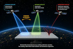
Make-before-break removes that gap by forming a second beam toward the incoming satellite and synchronizing on it while the first still carries traffic. That beam can come from a second panel, a second beamforming chain on the same aperture, or time-interleaved beam hopping at the cost of duty cycle. Splitting one aperture between two beams costs roughly 3 dB of gain per beam. Conventionally, concurrent beams must be paid for in hardware.
Accurate steering also depends on knowing the satellite’s actual location, not just where the ephemeris says it should be. Attitude sensor drift, mounting misalignment, thermal distortion, and residual calibration error all leave a pointing offset, and with narrow beams that offset is expensive: An error of half the half-power beamwidth costs 3 dB by definition.
Monopulse tracking using the subarrays closes the loop: the aperture forms a sum beam and one or two difference beams at the same time, and the ratio of difference to sum gives a signed angle-error estimate that’s largely independent of received signal level. In a hybrid array, those patterns are just two weight sets applied to subarray outputs, so fine pointing costs digital combining rather than RF hardware.
As arrays grow further, distributed digital beamforming (DDBF) becomes increasingly attractive. Rather than sending raw data to a central processor, processing is done locally within antenna tiles, each integrating antenna elements, RF front-end circuitry, data converters, and local digital processing, with partially processed signals combined by higher-level beamformers over high-speed serial links (Fig. 2).
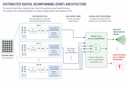
In practice, those are JESD204-class interfaces (JESD204B or JESD204C), the established standard between data converters and digital logic, which add deterministic latency and multi-lane synchronization. Therefore, tile outputs arrive with a known, repeatable sample alignment rather than merely a known bit rate; coherent combining depends on the tiles agreeing on time. A 64-element Ka-band receive panel, for example, can be built as an 8x8 patch aperture served by four analog subarrays, each with its own digital beamformer, interconnected over JESD204B.
Because each tile sends out an already-combined signal instead of raw element data, the interconnect carries far less traffic than a centralized digital array would, and extra tiles can be added without widening a central bus. Clocking benefits, too: Instead of routing a high-frequency Ka-band local oscillator across the panel, a low-frequency reference is distributed and multiplied up by phase-locked loops (PLLs) inside each tile. LO paths stay short; only digitized signals and a reference clock cross the array, and the array grows by replicating identical tiles.
This structure also helps with handover. Because each tile has its own digital processing, a second beam is created by applying another set of weights to the tile outputs rather than by adding RF chains or a second panel. Thus, concurrent beams become a software choice rather than a build-time one. The aperture can be shared for the few seconds of an overlap window and returned to a single full-gain beam immediately afterwards, making the 3-dB penalty temporary rather than designed in.
Each tile also keeps its own calibration and timing, so a newly assigned beam is coherent as soon as it’s formed. The incoming link can be verified before the outgoing one is released at the cost of a little extra digital logic inside the tile rather than a second aperture and a second set of front ends.
System-Level Benefits of Distributed Architectures
Distributed architectures also bring advantages beyond data movement. Coherent combining across elements improves signal-to-noise ratio (SNR) by the array gain, 𝑆𝑁𝑅_𝑎𝑟𝑟𝑎𝑦 ≈ 𝑁 · 𝑆𝑁𝑅_𝑒𝑙𝑒𝑚𝑒𝑛𝑡, where 𝑁 is the number of antenna elements, so each doubling of coherently combined elements adds about 3 dB.
Because ADC quantization noise is largely uncorrelated between channels, combining suppresses it relative to the wanted signal, allowing lower-resolution ADCs at the element level, saving power and cost. Phase noise behaves similarly: Contributions from individual PLLs are partially uncorrelated, so the wanted signal adds coherently while phase noise averages, improving beam phase stability.
Spatial Processing and Interference Mitigation
Another major strength of subarrays using DDBF is spatial interference mitigation. Adjacent satellite interference is increasingly common, and large arrays can steer nulls toward unwanted sources while holding gain on the wanted one.
In hybrid architectures, this depends on the number of independent digital channels, which correspond to subarrays rather than elements. With 𝑁_𝐷𝐵𝐹 digital channels, roughly M ≈ 𝑁_𝐷𝐵𝐹 − 1 interference sources can be suppressed. More subarrays mean more spatial degrees of freedom, at the cost of complexity.
Minimum variance distortionless response (MVDR) beamforming and multiple signal classification (MUSIC) remain the standard tools. MVDR minimizes interference power while preserving the wanted signal, and MUSIC is used for high-resolution direction finding. Machine-learning methods are also being explored for direction-of-arrival estimation and adaptive beamforming.
Reflectors will remain efficient where high gain and aperture efficiency are the primary requirements. But the growth of LEO constellations and emerging multi-orbit networks is shifting the balance toward architectures that deliver agile beamsteering, wide-angle scanning, handover, and stronger interference mitigation.
Phased arrays, hybrid beamforming and DDBF all address these demands, and together they show that antenna design is no longer just an RF front-end problem — it’s closely coupled to digital processing, system partitioning and implementation scale. At EnSilica, we focus our innovation on silicon, algorithms, and reference designs that make these architectures practical at scale for satellite user terminals and payloads.
About the Author
 Ian Lankshear
Ian Lankshear
CEO, Ensilica
Ian Lankshear co-founded EnSilica in 2001. Under his stewardship, the company has enjoyed sustained growth based on market-led opportunities, innovation, and export success. Ian has a strong technical and commercial background covering semiconductors and adjacent markets.
Ian’s early career was in radar systems development for Siemens Plessey Systems. He moved into semiconductor development in 1996, working for Hitachi and then for Nokia. Ian holds a First-Class Honors degree in Electrical & Electronics Engineering.
Related
 Leaders Logo
Leaders relevant to this article: