What's the Difference Between Coaxial Connectors (Part 2)?
Download this article in .PDF format
This two-part series examines the coaxial connector, which is an often overlooked—but nonetheless vital—aspect of an RF/microwave application. Part 1 provided a general overview of connectors, as important parameters and terminology were discussed. In Part 2, we’ll continue by describing various types of coaxial connectors that are commonly used for RF/microwave applications.
Type-N and 7/16 DIN Connectors
As stated in Part 1, the Type-N connector was introduced in 1942. Still commonly used today, this connector, which employs threaded coupling, is known for its durability. Standard Type-N connectors perform to 11 GHz, while versions that perform to 18 GHz are offered by some connector suppliers. Furthermore, both 50- and 75-Ω versions are available. Type-N connectors are covered by the MIL-C-39012 specification.
The 7/16 DIN connector derives its name from its dimensions; the diameter of its inner conductor contact is 7 mm and the internal diameter of its outer conductor is 16 mm. These connectors are known for their superior return loss and intermodulation distortion (IMD) characteristics. The 7/16 DIN connector can cover a frequency range of dc to 7.5 GHz.
The SMA Connector and its Mates: 3.5- and 2.92-mm Connectors
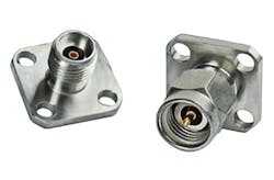
The SMA connector is widely used throughout the RF/microwave industry (Fig. 1). It originated in the late 1950s when James Cheal of Bendix Research Laboratories designed the Bendix real miniature (BRM) connector. The development of the BRM connector continued, leading to its incorporation into MIL-C-39012 in 1968. The connector was then designated the SubMiniature A, or SMA, connector.
Like the Type-N connector, the SMA connector—which has an impedance of 50 Ω—employs threaded coupling. Originally intended to be used with 0.141-in.-diameter semi-rigid coaxial cables, the SMA connector’s usage was later extended to flexible cables as well. As mentioned in Part 1, SMA connectors employ a solid dielectric. Furthermore, while standard SMA connectors perform from dc to 18 GHz, some suppliers provide versions that can perform to 26.5 GHz. Although they are common and inexpensive, SMA connectors have their limitations—they are rated for a very limited number of connection cycles.
The SMA connector is mechanically compatible with two other connector types: 3.5- and 2.92-mm connectors. Both of these employ an air dielectric and can perform at higher frequencies than their SMA counterpart. 3.5- and 2.92-mm connectors are both named after the inside diameter of their respective outer conductors.
The 3.5-mm connector, which can achieve mode-free performance to 34 GHz, first appeared in the 1970s. The connector was primarily developed at Hewlett-Packard (HP) and later manufactured by Amphenol. These connectors are known for their durability, as they were designed to allow thousands of repeatable connections.
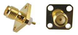
Introduced by Wiltron (now Anritsu) as the Type-K connector in 1983, the 2.92-mm connector is available today from a wide range of suppliers (Fig. 2). 2.92-mm connectors can be used at higher frequencies than 3.5-mm connectors, as they offer performance to 40 GHz. Measurement systems and high-performance components, for example, sometimes implement 2.92-mm connectors.
Higher-Frequency Connectors: 2.4-, 1.85-, and 1.0-mm
Even higher-frequency performance can be achieved by 2.4-, 1.85-, and 1.0-mm connectors. Like 3.5- and 2.92-mm connectors, 2.4-, 1.85- and 1.0-mm connectors employ an air dielectric. They also derive their names from the inside diameter of their respective outer conductors.
The 2.4-mm connector, which was developed in the mid-1980s, can achieve performance to 50 GHz. 2.4-mm connectors have a thick outer wall, thus making them less frail than SMA and 2.92-mm connectors. At first glance, it may be difficult to distinguish a 2.4-mm connector from a 2.92-mm connector. However, should one attempt to connect a 2.4-mm connector to an SMA connector, the difference will be very clear—the two connector types will not mate. Therefore, an appropriate adapter is needed to connect a 2.4-mm connector to either an SMA, 3.5-mm, or 2.92-mm connector.
In addition, the 1.85-mm connector can achieve mode-free performance to 65 GHz. HP developed the connector in the mid-1980s. The company then offered its design as public domain in 1988 for the purpose of standardizing connector types. 1.85-mm connectors can be mated with 2.4-mm connectors, but not with SMA, 3.5-mm, and 2.92-mm connectors.
Furthermore, millimeter-wave applications can take advantage of the 1.0-mm connector. This connector, which was also developed by HP, can achieve performance to 110 GHz. Probe stations are an example of an application that utilizes 1.0-mm connectors.
Not Forgotten—BNC and TNC Connectors
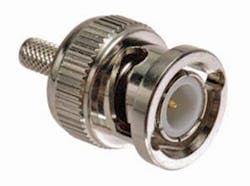
The widely used BNC connector has a typical frequency range of dc to 4 GHz (Fig. 3). Commonly used for test-and-measurement equipment, the BNC connector, which employs the bayonet-coupling technique, is offered with an impedance of either 50- or 75-Ω. Female connectors have two bayonet lugs and can be connected to male connectors with just a ¼-turn of the coupling nut. Unfortunately, BNC connectors are not usable above 4 GHz because they are prone to radiation at those frequencies. BNC connectors are covered by MIL-C-39012.
The TNC connector is a threaded version of the BNC connector, offering higher-frequency performance than its BNC counterpart. These connectors are typically rated to 11 GHz. Like the BNC connector, the TNC connector is covered by MIL-C-39012.
Conclusion
To summarize, a wide range of coaxial connectors are available to satisfy the demands of today’s high-frequency applications. This series discussed some of the commonly used connectors, but additional types exist that were not mentioned. Although connectors may seem mundane, they are crucial for any application. Thus, it is important to understand the basics of coaxial connectors and the many options that are available today.
Looking for parts? Go to SourceESB.
