Dual-Band Coupler Links With CRLH Lines
Couplers are critical components in communications systems, commonly used to isolate receivers from transmitters. They are also vital parts of test-and-measurement applications.1 In a communications system, for example, a coupler’s isolation is significant since poor isolation results in reduced receiver sensitivity and higher DC offset. A number of approaches have been used to improve isolation between coupler transmit and receive ports,2-6 but many of these techniques lead to larger circuits, and few apply to dual-band couplers.
To enhance the transmit-receive isolation of a dual-band coupler, a new design approach was investigated involving the use of composite right/left-handed (CRLH) transmission lines. To verify this novel design concept, a dual-band coupler for wireless-local-area-network (WLAN) applications at 2.4 and 5.0 GHz was designed and fabricated, then compared with a conventional branch-line coupler in terms of size and performance. Measurements of the new coupler indicate better than 53-dB coupled-port isolation within both frequency bands.
Figure 1 shows the basic principle and circuit configuration of the dual-band coupler with enhanced isolation. A cross-coupled branch-line coupler is the basis for the dual-band coupler.7 Signals for transmission are radiated by a dual-band antenna connected to port 1; it is also coupled at a lower level to port 2. Signals received by the antenna at port 1 are transferred to port 3, where they can be boosted in amplitude by a low-noise amplifier (LNA). To increase isolation, an intentional amount of impedance mismatch is introduced into idle port 4 to create a cancellation signal—one designed to have the same magnitude and opposite phase of the transmit leakage signals at the receive port. The cancellation and leakage signals sum to a net value of zero, resulting in total leakage of zero and high isolation between the transmit and receive ports of the coupler.
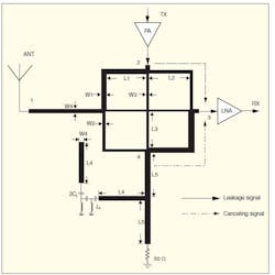
1. This diagram shows the principle and basic approach to the new coupler, with the power amplifier (PA) at the transmit port and low-noise amplifier (LNA) at the receive port representing additional system components.
To develop the required cancellation-signal characteristics, the relationship between the optimum reflection coefficient of idle port 4 and the S-parameters of the branch-line coupler must be derived. The S-parameters of a branch-line coupler can be found from Eq. 1:1
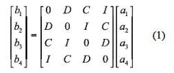
where:
C = the coupling factor;
D = directivity;
I = isolation;
an = an incident wave at the coupler’s nth port; and
bn = a reflected wave from the coupler’s nth port.
Since the reflection coefficient (Γa) of the antenna port can be measured, and the reflection coefficient of port 4 with the mismatch load can be assumed as Γ, the conditions of Eqs. 2 and 3 can be achieved:
a1 = Γab1 (2)
a4 = Γb4 (3)
By substitution, Eqs. 2 and 3 revert to Eq. 1. and the S-parameters of the branch-line coupler can be derived by Eq. 4:
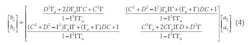
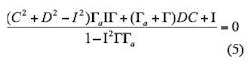
To properly isolate the receive port (port 3) from the transmit port (port 2), the value of the S32 parameter for port 4 should be zero, as shown by Eq. 5:
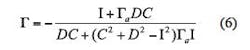
The required reflection coefficient of isolation port 4 can be found by using Eq. 5 to derive Eq. 6:
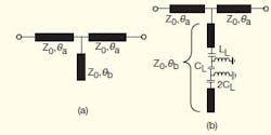
2. The structure in (a) achieves the required mismatch on port 4, while (b) is a method using a CRLH transmission line.
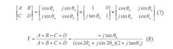
It is essential that the proper reflection coefficient at port 4 be found in order to achieve high isolation between the coupler’s transmit and receive ports. Figure 2(a) shows the structure required to achieve the intended impedance mismatch at port 4. A shunt stub has been tapped to the center of the feedline of port 4, where parameters Z0, θa, and θb represent the characteristic impedance, the electrical length of the series section, and the electrical length of the stub section, respectively. The characteristic impedance and the port impedances are equal to 50 Ω and are normalized to 1, so that the ABCD matrix of the T-shaped circuit can be written as Eq. 7 (see below), with each element of the ABCD matrix given by these simple equations:
A = D = cos2θa– sin2θa– sinθacosθatanθb
B = 2jsinθacosθa– jsin2θatanθb
C = 2jsinθacosθa+ jcos2θatanθb
The reflection coefficient for the coupler’s port 4 can then be found by applying Eq. 8 (see below).
Once the electrical length of the series stub (θa) has been confirmed, the electrical lengths of the shunt stub (θb) can be computed.
To derive the same value of reflection coefficient at port 4 for two arbitrary frequencies, a CRLH transmission line has been used for the shunt stub, as shown in Fig. 2(b). The CRLH transmission line is composed of a left-handed section implemented by two cascaded T networks, with the right-handed transmission line having a specified length. By choosing the appropriate CRLH transmission-line parameters L4, CL, and LL, the required characteristic impedance (Z0) and electrical length (θb) can be found at two arbitrary frequencies,8 and high transmit-receive-port isolation can be achieved in both frequency bands.
If the operating frequencies of the coupler’s two bands are designated as f1 and f2, the electrical lengths of the series stub and the shunt stub will be θal, θb1at f1, and θa2, θb2 at f2. The relationship between θa1and θa2 can be approximated by Eq. 9:

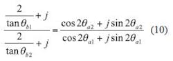
Since the reflection coefficient for port 4 is the same at f1 and f2, Eq. 10 follows from Eq. 8:
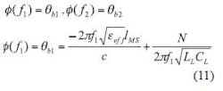
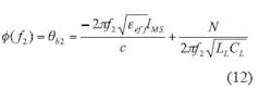
Since the electrical lengths for θa1, θa2, and θb1are known, the electrical length of θb2can be found from Eq. 10. The phase response of the CRLH transmission line at f1 and f2 is confirmed8 by Eqs. 11 and 12:
where:
lMS = the physical length of the RH microstrip line;
N = the number of unit cells in the LH transmission line;
LL = the shunt inductor of the LH transmission line; and
CL = the series capacitor of the LH transmission line.
Once IMS has been found, the values of LL and CL can be found.
Using these parameters, a prototype dual-band coupler was fabricated to confirm the validity of the design approach. It was created by following these five steps:
1. Calculate the circuit parameters of the cross-coupled branch-line coupler from ref. 7.
2. According to the required coupling factor (C) and reflection coefficient (Γa) for the antenna port—in addition to the coupling factor (C), directivity (D), and isolation (I) of the branch-line coupler—calculate the reflection coefficient of the impedance mismatch for port 4.
3. At frequency f1, specify the electrical length of the series stub, θa1, in advance. Find the electrical length of the shunt stub, θb1, from Eq. 8 and the series stub, θa2, at frequency f2 from Eq. 9.
4. Solve Eq. 10 for the electrical lengths of the shunt stub θb2at f2 by substituting the values of θa1, θa2, and θb1into Eq. 10.
5. Determine the physical length, IMS, using standard microstrip formula and the LH transmission-line parameters LL and CL from Eqs. 11 and 12, respectively.
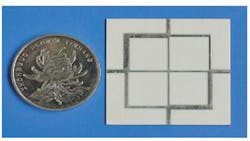
For comparison purposes, a conventional dual-band branch-line coupler was designed for use at 2.4 and 5.0 GHz, to serve as a reference for the improved design. It was constructed on RO 4003™ circuit material from Rogers Corp. (www.rogerscorp.com) with thickness of 0.508 mm and relative dielectric constant of 3.38 in the z direction at 10 GHz. The circuit parameters for the cross-coupled branch-line coupler were obtained from ref. 7. The coupler has circuit dimensions of W1 = 1.43 mm, W2 = 0.7 mm, W3 = 0.48 mm, W4 = 1.17 mm, L1 = 10.65 mm, L2 = 11 mm, and L3 = 10.65 mm. Figure 3 shows a photograph of the fabricated cross-coupled branch-line coupler, while Fig. 4 shows its measured S-parameters. This conventional coupler exhibits measured isolation of about 18 dB at 2.4 GHz and about 19 dB at 5 GHz, mediocre performance.
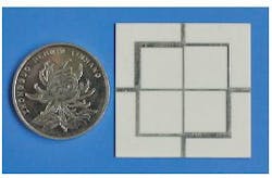
3. This conventional cross-coupled branch-line coupler was fabricated for comparison with the new coupler design.
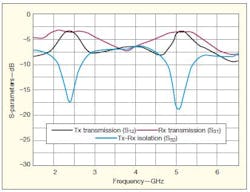
4. These plots show the measured S-parameters for the conventional coupler of Fig. 3.
Following the procedure described in the previous section, the theoretical parameters of the cross-coupled branch-line coupler with improved isolation were determined. The final circuit layout was optimized using the IE3D full-wave electromagnetic (EM) simulator from Zeland Software (www.zeland.com).9 The circuit parameters of the intended mismatch are L4 = 11.9 mm, L5 = 12.9 mm, LL = 18 nH, CL = 5 pF. Figures 5 and 6 show a photograph of the coupler and the measured S-parameters of the cross-coupled branch-line coupler with improved isolation.
5. This is the cross-coupled branch-line coupler with improved isolation.
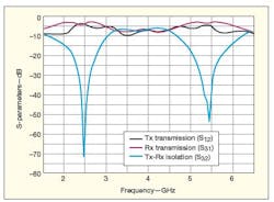
6. The new coupler achieves high port-to-port isolation.
Within the first frequency band of 2.4 GHz, the coupler has 4-dB transmit-port transmission loss, 3.6-dB receive-port transmission loss, and 65-dB transmit-receive-port isolation. Within the second frequency band at 5 GHz, the coupler has 4.1-dB transmit-port transmission loss, 3.4-dB receive-port transmission loss, and 53-dB transmit-receive-port isolation. The measured results verify that the proposed coupler design significantly improves transmit-receive-port isolation within both bands, compared with the performance of a conventional dual-band coupler shown in Fig. 4.
In summary, by realizing an intended impedance mismatch at the coupler’s idle port, isolation between the coupler’s transmit and receive ports can be significantly increased. To demonstrate the concept, a prototype coupler was fabricated and measured. Luckily, it is both compact and simple to fabricate.
References
1. David M. Pozar, Microwave Engineering, 2nd ed., Wiley, New York, 1998.
2. S.K. Cheung. T.P. Halloran, W.H. Weedon, and C.P. Caldwell, "MMIC-Based Quadrature Hybrid Quasi-Circulators for Simultaneous Transmit and Receive," IEEE Transactions on Microwave Theory & Techniques, Vol. 58, No. 3, March 2010, pp. 489-497.
3. W.K. Kim, M.Q. Lee, J.H. Kim, H.S. Lim, J.W. Yu, B.J. Jang, and J.S. Park, "A Passive Circulator with High Isolation Using a Directional Coupler for RFID," IEEE Microwave Theory & Techniques Symposium International Digest, 2006, pp. 1177-1180.
4. J.R. Yang, D.W. Kim, and S. Hong, "Quasi-circulator for effective cancellation of transmitter leakage signals in monostatic six-port radar, IEEE Transactions on Microwave Theory & Techniques, Vol. 45, No. 21, October 2009, pp. 1093-1095.
5. K. Kim and D. Ahn, "A new switching structure using branch-line hybrid couplers for time-division-duplex system," IEEE Microwave Theory & Techniques Symposium International Digest, 2008, pp. 999-1002.
6. S.G. Kim, H. Kim, Y. Lee, S. Kho, and J.G. Yook, "5.8-GHz Vital Signal Sensing Doppler Radar Using Isolation-Improved Branch-Line Coupler," Third European Radar Conference, 2006, pp. 249-252.
7. M.J. Park and B. Lee, "Dual-Band, Cross-Coupled Brach-Line Coupler, IEEE Microwave and Wireless Components Letters, Vol. 15, No. 10, October 2005, pp. 655-657.
8. C. Caloz and T. Itoh, Electromagnetic Metamaterials: Transmission Line theory and Microwave Applications. Hoboken, NJ: Wiley, 2006.
9. IE3D Version10.1, Zeland Software, Inc. (www.zeland.com).
