Conductive RF Test Environments Boost Confidence in UE, SoC, and Chipset Designs

Verifying RF performance at every stage of the ecosystem requires a new test approach to keep pace with the market changes. A more repeatable methodology than over-the-air (OTA) is necessary to conduct measurements efficiently and accurately for the new wireless age. Such a test environment may also provide greater cost efficiencies than traditional radio channel emulators/simulators.
Emulated Real-World Environment
A conductive environment built on an RF hardware platform can be agnostic to the underlying baseband technology and support analysis of multiple wireless standards. It can also test designs with multiple channels, such as 4x4 MIMO Wi-Fi base stations and cellular base stations having as many as 96 channels. Such flexibility and adaptability are necessary, as mobile devices, use cases, and wireless technologies vary based on expanding applications.
Key differentiators of a conductive test environment comprise the transmitted and received signals that will travel through RF devices, components, and distribution elements during testing. Those components, such as attenuators, phase shifters, filters, power dividers/combiners, couplers, antennas, coaxial transmission lines, and channel matrices, control and manipulate the signals in the test environment, creating an authentic representation of a channel.
A test configuration utilizing RF components also gains an important property of passive RF networks — their reciprocity. So, regardless of the direction of signal propagation in the system, the transmission parameters remain the same.
Conducted vs. OTA Testing
In OTA testing, a device is verified in a variety of real-world scenarios that match expected use cases. While this form of testing can provide confidence that the device will function as expected, conductive testing offers multiple benefits versus OTA in certain environments.
>>Download the PDF of this article

A conductive test is repeatable; the conditions that produced a failure can be precisely logged and reproduced. Complex signal environments, including multipath fading and interferers, are able to be emulated in a conductive environment.
Channel Emulators/Simulator Considerations
Numerous test scenarios that would be conventionally performed by a channel emulator are achievable with a conductive test environment. These test environments can include multipath fading models and the emulation of specific multiple-in, multiple-out (MIMO) channel conditions.
By implementing the test environment with RF components, cost savings can be realized. As the number of MIMO channels in systems increases, such savings may prove to be significant. Minimum path delay could be significantly reduced, too.
Another important difference is that a channel emulator regenerates the signal, while a conductive environment directly conducts it. This means that the RF interface between a base station and a user equipment (UE) can be directly characterized, without the signal characteristics being inadvertently improved by the regeneration.
Effective Building Blocks
The correct hardware building blocks must be selected to accurately recreate the environment the device will experience under operation. The figure shows a simple test setup for characterizing the throughput of a Wi-Fi device in a conductive environment.
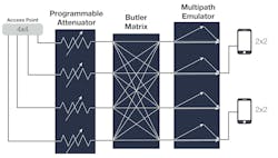
Traffic is sent from the base station to the UEs and vice versa. The attenuator is varied to characterize the performance of the devices in different conditions. An analogous setup could be created for cellular or any other wireless communication standard.
The multichannel programmable attenuator is used to vary the path loss of the emulated channel. It’s important to select an attenuator with sufficient dynamic range to ensure that the device under test (DUT) will see path losses across the expected range of operation. Often, for Wi-Fi and 5G testing, 95 dB will be sufficient. In some cases, however, the need arises for dynamic ranges of >120 dB.
A Butler matrix is a device in which each input connects to each output, and the relative phase shift between each port is 180/n, where n is the number of ports. Intuitively, this phase shift replicates the physical spacing between the antennas that would be present in an OTA MIMO channel.
Unused ports can be terminated, allowing for a dissimilar number of physical channels to be connected, and the device is passive and reciprocal. And multiple base stations could be connected to a single Butler matrix for modeling a handover between base stations.
Multipath is a phenomenon where a signal is able to travel directly between a transmitter and a receiver, or it can reflect off an object and be delayed. On an RF level, this could lead to a pattern of destructive and constructive interference. Indoor and some outdoor multipath can be emulated using RF hardware.
Compared to a conventional channel emulator, this approach typically brings significant cost savings and reduced insertion delay. This approach also has several disadvantages, as the supported channel models are fixed at system build and will be time invariant.
It may be required to insert fixed attenuators into a conductive test setup. High-power fixed attenuators will be needed to reduce the output power from a cellular base station, so that the equipment downstream isn’t damaged. Lower-power fixed attenuators may be required to reduce the power received by the UEs to such a level that the receivers will not be saturated.
Key Measurements for Verification
While a certain level of customization is associated with these test systems for the respective application, key parameters must be tested regardless of use case. Below are critical measurements that should be performed on mobile devices and network elements, and they can be made using conductive test environments. Test systems should perform these measurements in controlled environments:
- Throughput: The throughput of multiple wireless devices needs to be tested at various transmit and receive power levels. Test systems must support multiple wireless technologies, such as 5G, LTE, Bluetooth, and Zigbee, to verify the performance of modern UE.
- Handover testing: A key measurement, handover testing determines the effective transfer of signals between base stations and devices to ensure transmissions aren’t dropped.
Handover testing is a prime example of the effectiveness of a conductive test system utilizing RF components. The radios under test are connected to power dividers/combiners, then to multichannel programmable attenuators. Finally, the signal is routed to a number of UEs. Motion can be emulated by ramping the attenuators to introduce signal loss versus time. The ramping rate can be accurately controlled to mimic the typical velocity of mobile devices when in vehicles.
Conclusion
Emerging market conditions are creating scenarios where no two wireless networks are alike, and a UE can be used in a variety of applications. There are growing private networks for IoT use cases that create significant design and verification challenges.
A conductive test environment is an efficient and effective approach to verify the performance of UE, base stations, and chipsets in diverse and emerging environments. Devices in a conductive test environment can mimic a variety of nodes or impairments in a network, resulting in more accurate testing and greater design confidence.
>>Download the PDF of this article
About the Author
Manhphat Nguyen
, Senior Consultant RF Engineer (Aerospace & Defense Systems), Spectrum Control
ManhPhat Nguyen is Senior Consultant RF Engineer (Aerospace & Defense Systems) for Spectrum Control, where he directs the end-to-end technical design and development of mission-critical RF components and subsystems. His expertise extends to MIMO and beamforming capabilities to meet stringent performance requirements in complex operational environments for both commercial and defense sectors.
