This file type includes high resolution graphics and schematics when applicable.
Vector network analyzers (VNAs) are workhorse measurement instruments for engineers involved in RF/microwave electronics and precise characterization of amplitude and phase, and they have gone through many developments and enhancements over the past few decades. The latest development is a line of VNAs that each fit into single PXIe modules for measurement flexibility and adaptability.
The six modules are available for use across a total frequency range of 300 kHz to 26.5 GHz. The new two-port VNA PXIe modules are members of the M937XA series, hailing from a new name in RF/microwave measurements: Keysight Technologies. The firm has itself evolved from a long-trusted name in high-speed and high-frequency measurements, Agilent Technologies.

Evolution in VNAs, for those old enough to remember, traces back to the standard rack-mount architecture of the HP 8409A; this would evolve into the legendary HP 8510A VNA. Both were introduced by Hewlett-Packard Co., a forerunner of Keysight predecessor Agilent. For those trying to keep track, last September Agilent Technologies revealed plans to separate into two publicly traded companies through a tax-free spinoff of its electronic measurement business.
The new spinoff company, Keysight Technologies, Inc., began operating as a wholly owned subsidiary of Agilent Technologies on August 1, 2014, and is expected to begin trading on the New York Stock Exchange (NYSE) as a totally separate public company beginning in early November 2014. If the M937XA series of PXIe VNAs is representative of the new products to be developed by Keysight, there will be long lines at the NYSE to purchase the company’s stock.
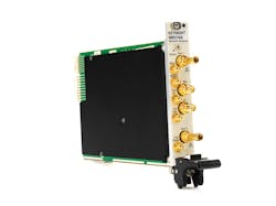
The M937XA VNAs (Fig. 1) build upon those early rack-mount VNAs, with each managing to fit the functionality of a two-port microwave VNA into a single PXIe module. Gregg Peters, vice president and general manager of Keysight’s Component Test Division, notes: “With our new PXI VNA, we now offer a choice in form factor that addresses emerging needs in aerospace, defense, wireless communications, and more.” (For more on PXI, see “What is PXI?”)
Each module features a pair of high-density printed-circuit board (PCBs) and includes a precision signal source for the appropriate frequency range. The modularity and flexibility allows engineers to add two ports of VNA measurement capability at a time, with as many as 16 VNA modules contained within a PXI/PXIe chassis for a total of 32 fully synchronized VNA measurement ports. The six new VNA modules in the M937XA series are model M9370A (300 kHz to 4.0 GHz); model M9371A (300 kHz to 6.5 GHz); model M9372A (300 kHz to 9.0 GHz); model M9373A (300 kHz to 14.0 GHz); model M9374A (300 kHz to 20.0 GHz); and model M9375A, 300 kHz to 26.5 GHz.
Clearly, a user can select just the frequency range needed, then assemble the number of modules required for a sufficient number of test ports. Even for seemingly simple RF/microwave passive component testing, such as characterizing a four-way power divider, more than four test ports are needed across the frequency range of interest. The M937XA series of VNAs enables companies to add measurement capabilities as needed even as their own product lines expand.

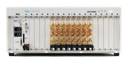
All ports are fully synchronous so that all ports can be measured simultaneously and multiport error correction can be applied. This capability to increase measurement capabilities by simply adding modules to an equipment chassis can greatly simplify a high-frequency measurement setup while reducing the requirements for test-equipment space in a laboratory (Fig. 2) or production line.
Each M937XA series module is a four-receiver, two-port VNA. Although compact, they do not scrimp on performance, with standard leveled power ranges of -40 to +7 dBm from their built-in test sources, adjustable with 1-dB resolution. In fact, the compact VNA modules are capable of delivering as much as +7 dBm leveled test power for measurements on a wide range of active and passive components, subsystems, and systems.
These VNA modules boast amplitude stability of better than 0.020 dB/°C from 300 kHz to 26.5 GHz, with trace noise of less than 0.003 dB. They are capable of dynamic range of better than 114 dB at 9 GHz and better than 110 dB at 20 GHz. Each VNA module can achieve sweep speeds of 18 ms across 401 points and can capture as many as 16,001 total measurement points.
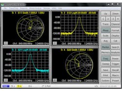
The M937XA series VNA modules employ the same user interface and SCPI programming commands (Fig. 3 and 4) as the benchtop PNA line of RF/microwave network analyzers popularized by Agilent Technologies and now offered by Keysight Technologies. This provides a simple transition to these new modules for users familiar with PNA instruments.
The new PXI/PXIe VNAs also use the same measurement science and calibration routines used in the PNA line of microwave network analyzers, including through-reflect-line (TRL), short-open-load-through (SOLT), and other calibration routines that have proven their values in earlier vector analyzers from Agilent Technologies. The PXI/PXIe VNAs are also available with a wealth of calibration support and guidance. They are compatible with a host of mechanical calibration kits from various vendors—as well as the ECal kits now available from Keysight—to simplify the process of calibrating a measurement setup with any number of VNA modules, whether in a single chassis or in multiple PXI/PXIe chassis.
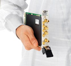
The modular VNAs are also available with a wide range of software options, including time-domain analysis capability, N-port calibrations, and capabilities in support of advanced test fixture/simulator setups. The small size of these PXI/PXIe modules (Fig. 5) makes it possible to assemble complete measurement systems in the area once occupied by a single RF/microwave measurement instrument, and with a price per test port that is a fraction of the cost of traditional RF/microwave test equipment. It is not difficult to understand the growing interest in modular measurement solutions such as PXI/PXIe in the RF/microwave industry.
This file type includes high resolution graphics and schematics when applicable.
What is PXI?
This file type includes high resolution graphics and schematics when applicable.
A number of different modular architectures have been developed over the years in support of electronic instrumentation, including PXI, which is an abbreviation for PCI eXtensions for Instrumentation. Building upon the available computer buses at the time, PXI was originally developed by and introduced by National Instruments in 1997. It is now backed by a large group of test-and-measurement companies as part of the PXI Systems Alliance (PXISA).
The group oversees the use of PCI technology within hardware and software manufactured to the PXI standards. A typical 3U PXI module measures about 4 × 6 in. (100 × 160 mm). A typical full rack-mount PXI chassis is 4U high and holds as many as 18 PXI slots. The global market for PXI products is expected to grow steadily; it is larger than the global markets for VME eXtensions for Instrumentation (VXI) and local-area-network (LAN) eXtensions for Instrumentation (LXI) modular instrument products.
With the growth in modular measurement solutions, PXI Express (PXIe) was developed in 2005 as a compatible chassis/module format that could also support faster data rates (to 6 GB/s). A PXIe chassis supports the use of hybrid module slots, compatible for use with both PXI and PXIe modules. PXI modules are register-based circuits that work with software drivers hosted on a personal computer (PC) or on an embedded controller contained in the PXI/PXIe chassis.
PXI/PXIe systems are compatible with a range of PC operating systems, including Microsoft Windows Vista SP1 and SP2, along with Microsoft Windows 7. They are also compatible with IVI-COM, IVI-C, LabVIEW, and MATLAB drivers, and with a range of application development environments that includes Visual Studio, LabVIEW, MATLAB, VEE, and LabWindows/CVI. PXI/PXIe modules and systems incorporate many common interface buses for flexibility, such as Universal Serial Bus (USB) connections, enabling electronic calibration (eCal) control via USB interface.
A PXI chassis may include its own controller running a standard operating system, such as Microsoft Windows XP or Windows 2000, or a PCI-to-PXI bridge that provides a high-speed link to a desktop PC controller. To build large systems, multiple PXI/PXIe racks can be linked by means of PCI bridge cards. The PXI/PXIe chassis provides the power, cooling, and communication buses for a PCI/PCIe controller and modules.
Although they are also compatible, the PXI and PXIe specifications each carry their own lists of operating parameters. For example, the PXI specification requires that a minimum of 25 W of power be available to each peripheral slot. In contrast, the PXI Express specification boosts the minimum power level a bit, to 30 W, with each slot capable of dissipating the same amount of heat.
This file type includes high resolution graphics and schematics when applicable.
About the Author
Jack Browne
Technical Contributor
Jack Browne, Technical Contributor, has worked in technical publishing for over 30 years. He managed the content and production of three technical journals while at the American Institute of Physics, including Medical Physics and the Journal of Vacuum Science & Technology. He has been a Publisher and Editor for Penton Media, started the firm’s Wireless Symposium & Exhibition trade show in 1993, and currently serves as Technical Contributor for that company's Microwaves & RF magazine. Browne, who holds a BS in Mathematics from City College of New York and BA degrees in English and Philosophy from Fordham University, is a member of the IEEE.
