Establishing Phase Reference Standards for RF Cable Assemblies: Design, Test, and Production Control
What you'll learn:
- How electrical length provides a more direct metric than absolute delay for phase control in RF cable assemblies.
- Why velocity-factor variation can break physical-length specifications even when phase appears to be matched.
- Which design, test, and production controls are critical to maintaining batch-to-batch phase consistency?

High-frequency systems such as phased-array radar, satellite communications ground stations, antenna arrays, and multi-port test platforms rely on tight inter-channel phase alignment to function correctly. In these applications, even small phase deviations between signal paths can degrade beam pointing accuracy, reduce gain, or compromise measurement integrity.
Thus, RF cable assemblies require not only compliance with insertion loss or impedance specifications, but also a clearly defined and repeatable phase reference.
Applications Requiring Phase-Consistent Cable Assemblies
Phase-consistent RF cable assemblies — where the phase difference between multiple cables is stable and tightly controlled — are used wherever phase synchronization is critical. In phased-array radar systems, beamsteering is achieved by controlling relative phase across many antenna elements. Phase inconsistency in cable assemblies directly degrades beam accuracy and angular resolution.
Satellite communication and navigation systems also depend on precise multichannel phase alignment to ensure coherent signal combining and resistance to interference. Similar requirements arise in electronic-warfare systems, where multi-beam jamming effectiveness depends on accurate phase control. Large antenna arrays and high-speed communication systems likewise rely on phase-coherent interconnects to maximize throughput and minimize distortion.
In test and measurement environments, such as multi-port vector network analyzer (VNA) setups, phase-matched cable assemblies are required to calibrate channel delays and ensure repeatable, comparable measurements across ports. This is particularly important for batch testing of components where relative phase is a key parameter.
Why a Phase Reference is Necessary for RF Cable Assemblies
A phase reference for RF cable assemblies serves as the baseline against which production, inspection, and acceptance testing are performed. Its primary purpose is to ensure phase consistency within a production batch and across multiple batches delivered over time. Without a defined reference, phase matching becomes subjective, increasing the risk of system-level integration problems.
A well-defined phase reference establishes a predictable performance envelope for high-frequency systems. It provides a quantitative benchmark that prevents excessive phase deviation from degrading system performance, such as beam misalignment in radar or loss of coherence in communication links.
>>Download the PDF of this article, and check out the TechXchange for similarly themed articles and videos


Phase references also enable batch consistency and interchangeability. In multichannel systems, uniform phase behavior across cables prevents mismatch during integration and simplifies replacement or expansion. A common reference further allows objective comparison between suppliers or production lots.
Finally, a phase reference defines clear test conditions and acceptance criteria. By specifying frequency, temperature, and mechanical state, it becomes the yardstick for production control and dispute-free acceptance between supplier and integrator. Environmental sensitivity, such as temperature- or bend-induced phase variation, can also be incorporated into the reference to ensure stability under real operating conditions.
Delay vs. Electrical Length in RF Cable Assemblies
Phase behavior in transmission lines can be described using either propagation delay or electrical length. Propagation delay is the absolute time required for a signal to travel from one end of a cable to the other, typically expressed in nanoseconds. It depends on the physical length of the cable and the dielectric constant of the insulating material, and it’s largely independent of frequency.
Electrical length, by contrast, is a normalized representation of delay relative to the signal period. It expresses how much phase shift is experienced by a signal as it propagates along the cable, commonly in degrees or fractions of a wavelength. Electrical length is directly proportional to delay multiplied by frequency, making it equivalent to phase angle.
Because electrical length maps directly to phase, it’s generally a more intuitive and accurate metric for production testing of phase-matched cable assemblies. Using delay alone requires frequency conversion to determine phase, which introduces additional measurement uncertainty. Electrical length therefore provides a clearer link between test results and system-level phase requirements.
Propagation Velocity and Velocity Factor in RF Cable Assemblies
Electromagnetic waves propagate at the speed of light in free space, but their velocity in a transmission line is reduced by the dielectric material. This propagation velocity is inversely proportional to the square root of the dielectric constant. The velocity factor, expressed as a percentage of the speed of light, is commonly used to characterize this effect. Table 1 summarizes the correspondence between velocity factor and dielectric constant for typical RF transmission lines.
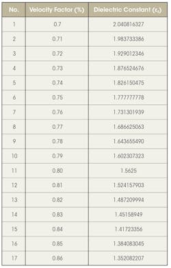
Small variations in dielectric constant lead to corresponding changes in velocity factor, which directly affect electrical length. For RF cable assemblies, this relationship means that even when physical length is held constant, differences in dielectric properties between cable lots can introduce phase variation.
Frequency, Wavelength, and Phase in RF Cable Assemblies
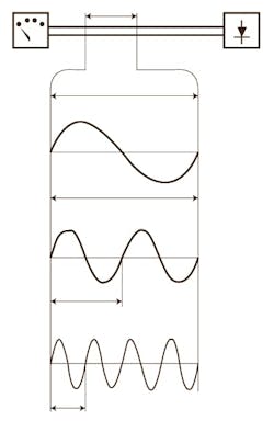
Wavelength is determined by both signal frequency and propagation velocity. As frequency increases, wavelength decreases, making phase increasingly sensitive to small dimensional or material variations.
The figure illustrates the inverse relationship between frequency and wavelength in a transmission line and highlights why higher-frequency systems place tighter demands on phase control. Electrical length can be expressed as a function of physical length, frequency, and dielectric constant, linking phase behavior to both design parameters and material properties.
Environmental Effects on Phase Stability
Phase stability is influenced not only by material properties, but also by environmental conditions. Temperature changes alter dielectric constant and physical dimensions, resulting in phase drift. Mechanical stress, such as bending, similarly affects electrical length. International standards like IEC 61196-1-111 describe test methods for evaluating temperature- and bend-induced phase variation, and these methods can be applied to RF cable assemblies.
For a phase reference to remain valid, manufacturing, testing, and storage conditions should be controlled. Fixed coiling diameters and stable ambient temperatures help ensure that measurements remain reproducible throughout production.
Impact of Velocity Factor Variation: Practical Examples
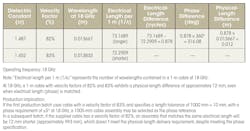
To illustrate the impact of velocity factor variation, consider a 1-meter cable assembly evaluated at two velocity factors: 82% and 83%. As shown in Table 2, at 18 GHz, this 1% difference in velocity factor produces an approximately 12-mm difference in physical length for the same electrical length. Although the electrical phase target is met, the resulting physical-length discrepancy can exceed mechanical tolerances.
The same behavior appears at lower frequency. Table 3 shows that at 6 GHz, the same 1% velocity-factor change again results in an approximately 12-mm physical-length difference for a 1-meter assembly. The equal magnitude of this discrepancy at both frequencies demonstrates that the phase deviation is governed by velocity factor rather than operating frequency.
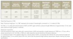
These examples demonstrate that phase deviation depends primarily on velocity factor rather than frequency. As a result, specifying electrical length alone is insufficient for ensuring consistent physical dimensions across batches. Velocity factor limits must also be defined to maintain both phase and mechanical compliance.
Designing and Defining the Phase Reference Assembly
A robust phase reference assembly must explicitly define velocity factor, electrical length, and physical length. Production specifications should constrain dielectric consistency across cable lots and require stable environmental conditions during fabrication, testing, and storage. By doing so, both phase alignment and dimensional requirements can be met consistently across batches.
In conclusion, phase reference standards are critical to ensuring the performance, reliability, and interchangeability of RF cable assemblies used in high-frequency systems. By prioritizing electrical length over absolute delay, controlling velocity factor variation, and stabilizing environmental conditions during production and testing, manufacturers can achieve consistent phase behavior across batches and over time. A well-defined phase reference bridges the gap between compliant components and reliable system integration.
Reference
IEC 61196-1-111, Coaxial communication cables – Determination of phase stability under temperature and mechanical stress.
>>Download the PDF of this article, and check out the TechXchange for similarly themed articles and videos
About the Author
Gang Xu
RF Connector Design Engineer, Sipu RF Technology Co., Ltd.
Gang Xu, M.S., is an RF Connector Design Engineer at Sipu RF Technology Co. Ltd.
Yingke Chang
RF Connector Design Engineer, Sipu RF Technology Co. Ltd.
Yingke Chang, B.S., is an RF Connector Design Engineer at Sipu RF Technology Co. Ltd.
Yan Guo
RF Connector Design Engineer, Sipu RF Technology Co. Ltd.
Yan Guo, B.S., is an RF Connector Design Engineer at Sipu RF Technology Co. Ltd.
Shihui Dai
RF Connector Design Engineer, Sipu RF Technology Co. Ltd.
Shihui Dai, B.S. , is an RF Connector Design Engineer at Sipu RF Technology Co. Ltd.
