Compliant 3D-Printed Mechanism Produces Deformable, Tunable GHz-Range Antenna
This article appeared in Electronic Design and has been published here with permission.
This article is part of the TechXchange: Antenna Design.
What you’ll learn:
- Why this deformable antenna has advantages compared to a foldable origami antenna.
- How the team designed and fabricated this iris-patch antenna design using 3D printing.
- The performance they modeled and measured up to 10 GHz.
Many situations arise in which an antenna needs to dynamically reconfigure its center frequency or beam pattern. In some cases, this can be done with a steerable, multi-element antenna array, but it’s often not a viable solution for various reasons.
As an alternative, a team of electrical engineers in the Penn State College of Engineering devised an innovative design for a reconfigurable patch antenna dubbed a reconfigurable compliant mechanism antenna (rCMA). The antenna, which leverages the inherent elastic properties of selected material to create a desired motion through controlled deformation, is designed to operate up to 10 GHz.
These compliant mechanisms can be made as a planar structure from a single material yet still achieve multi-axis motion. Further, they can be designed as a full structure with minimal or even no assembly, require no lubrication, and their reliability is high, as it’s based on the elastic properties of the material.
More Robust Origami-Type Antenna
The team acknowledges that this isn’t the first or only mechanically compliant antenna, but they say their compliant mechanism-enabled designs supersede existing origami-antenna (OA) design approaches. Those are reconfigurable but do not have the same advantages in robustness, long-term reliability, and power-handling capability.
Team member Galestan Mackertich-Sengerdy (a doctoral student and a full-time researcher in the department) noted that “origami-antenna designs are known for their compact folding and storage capabilities that can then be deployed later on in the application. But once these origami-folded structures are deployed, they usually need a complex stiffening structure, so that they don’t warp or bend. If not carefully designed, these types of devices would suffer environmental and operational lifetime limitations in the field.”
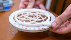
To accomplish their objective, the team designed a circular, iris-shaped patch antenna prototype using commercial electromagnetic-simulation software (Fig. 1). Then they 3D-printed it and tested it for fatigue failures as well as frequency and radiation pattern fidelity in Penn State’s anechoic chamber.
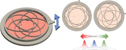
1. Overview of the proposed reconfigurable CMA (rCMA) operation: Shown is the simplified operation as well as targeted antenna characteristics of the system. As the top section is rotated, the arms displace, thereby changing the location of the shorting pins symmetrically around the center of the patch antenna. This changes the resonant frequency of the system, creating an operational frequency band for that configuration. Because the system is in continuous motion, it has continuously varying frequency reconfiguration. This motion is repeatable. Due to the fixed rotation limit as well as the elastic properties of the material, the displaced arms rebound back to their original state, but also allow for a high cycle lifetime.
The prototype—designed to target a specific frequency for demonstration—is only slightly larger than a human palm, but it can be scaled to the integrated-circuit level for higher frequencies or increased in size for lower-frequency applications, according to researchers. This initial version is manually operated; however, adding a controllable mechanism for operation is a likely next step (Fig. 2).
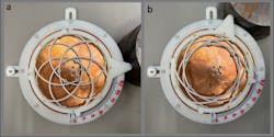
2. Fabricated rCMA with the top radiating patch section removed to observe the motion. Shown is the (a) relaxed configuration and (b) extended configuration. The repeated path that the shorting pins take along the copper ground plane is clearly visible in the photographs.
Their reconfigurable compliant-mechanism antenna is based on a simple, circular, shorted patch antenna. A custom, multi-leaf, spring-compliant iris was designed to guide its six shorting pins to travel, in contact, along the bottom ground plane and the upper radiating-patch element (Fig. 3). The compliant mechanism allows for continuously variable reconfiguration of the antenna’s resonant frequency through a simple mechanical action.
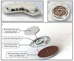
3. Renderings of the proposed rCMA: (a) Cutaway view of the entire rCMA revealing the custom shorting pins, the overlapping iris arms to allow motion and the feed pin in contact with the top radiating patch. (b) The top plate of the CMA is removed showing the orientation of the shorting pins in the smallest-diameter configuration.
They chose Verowhite from Stratasys for the 3D additive-manufacturing printable material. It offered the required RF properties, including low loss across the large range of frequencies, as well as the required mechanical properties needed to achieve consistent operation without fracturing. Copper plates were bonded to the surface to metallize the ground and radiating patch regions.
Test Results
The compliant mechanism’s structure offers continuous frequency reconfiguration from 3.5 to 6.2 GHz with a radiation efficiency greater than 80%. Performance of the fabricated antenna was close to their simulated results. Among the many tests they ran were assessment of S11 and resonant peaks (Fig. 4) as well as gain (Fig. 5) at various cavity settings.
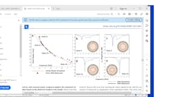
4. Measured S11 and resonant peaks compared against the estimated circular-patch radius based on the dielectric-loaded cavity model: (a) Ideal calculated patch radius corresponding to the given frequency with the traditional dielectric-loaded circular cavity model (red curve) compared against the measured resonant peaks extracted from the S11 data (black points). The dielectric-loaded circular-cavity model is bounded by perfectly magnetic conducting (PMC) walls, as well as two perfect electric conducting (PEC) surfaces on the top and bottom. (b-e) Shown are four shorting pin states, labeled in (a), and the comparison of measured S11 magnitudes versus simulated results. The cavity model is used to determine the dielectric loading as well as the maximal travel constraints of the shorting pins to achieve frequency reconfiguration. A full-wave finite-element-method (FEM) model is used to tune the shorting pin parameters and total heights as well as verify the estimated dielectric loading values. Image (c) is an exploded view of the rCMA, where the three main components are visible: the 3D-printed cap and radiating patch, the custom 3D-printed iris compliant mechanism and shorting pins, and the 3D-printed base with the ground plane and SMA antenna feed.
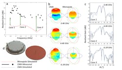
5. Simulated and measured antenna gain performance, including a static-monopole comparison. In (a), the reconfigurable CMA measured realized gain results clearly demonstrate higher gain than a traditional quarter-wavelength monopole antenna (image of both for comparison depicted in “d” showing similar total sizes) across the operational frequency band of both antennas. The simulated monopole antenna performance (a, b) was optimized for best results at a single height. A quarter-wavelength monopole operation is determined by its height, so it doesn’t permit any reconfigurability. It was chosen as the baseline for the comparison due to the similarity in radiation pattern shapes and total package volume. Three independent cases have been isolated. In (b), the rCMA and monopole simulated radiation pattern (color and size scaled per realized gain values) are presented at the three case frequencies. It can be seen that the reconfigurable CMA outperforms the static monopole in realized gain, as well as pattern shape retention. In (c), for the three cases chosen, the (φ = 0) simulated and measured (co-polarization) results for the reconfigurable CMA are compared and demonstrate good agreement with simulation, indicating the simulated 3D radiation patterns shown in (b) are accurate and can be expected in application.
The work is described in great detail in their 11-page paper “Tailored compliant mechanisms for reconfigurable electromagnetic devices” published in Nature Communications. There’s also a five-page posting of Supplemental Figures.
Read more articles in the TechXchange: Antenna Design.
About the Author

Bill Schweber
Contributing Editor
Bill Schweber is an electronics engineer who has written three textbooks on electronic communications systems, as well as hundreds of technical articles, opinion columns, and product features. In past roles, he worked as a technical website manager for multiple topic-specific sites for EE Times, as well as both the Executive Editor and Analog Editor at EDN.
At Analog Devices Inc., Bill was in marketing communications (public relations). As a result, he has been on both sides of the technical PR function, presenting company products, stories, and messages to the media and also as the recipient of these.
Prior to the MarCom role at Analog, Bill was associate editor of their respected technical journal and worked in their product marketing and applications engineering groups. Before those roles, he was at Instron Corp., doing hands-on analog- and power-circuit design and systems integration for materials-testing machine controls.
Bill has an MSEE (Univ. of Mass) and BSEE (Columbia Univ.), is a Registered Professional Engineer, and holds an Advanced Class amateur radio license. He has also planned, written, and presented online courses on a variety of engineering topics, including MOSFET basics, ADC selection, and driving LEDs.
