Reaching the Pinnacle in Helical Wrap-Wire Cabling Performance
Download this article in PDF format.
What you’ll learn:
- Improving fast Fourier transform (FFT) limits for better VSWR performance.
- How controlling mechanical properties ensures repeatable wrap-wire performance.
- Work collaboratively with a wire partner instead of a supplier.
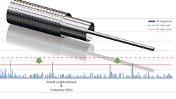
Like many of the elements of an electronic system, the wires that carry signals and/or power are more than the sum of their parts. Paying attention to the attributes of the components that comprise the cable has a significant impact on the finished cable’s performance. That’s true of all cables, but nowhere is it truer than for helical wrap cable wire (Fig. 1).
In this article, we’ll look at how improving fast Fourier transform (FFT) limits in the helical wrap material translates into better voltage standing-wave ratios (VSWR). We’ll also examine how controlling mechanical properties ensures repeatable wrap-wire performance. Finally, we’ll consider how working collaboratively with a wire partner is a surer path to design success than working with a supplier of wire and cable.
Improving FFT Limits for Better VSWR Performance
VSWR is the ratio of the maximum voltage to the minimum voltage in the standing-wave pattern along the length of a transmission-line structure. It’s used to measure differences in impedance. Managing VSWR levels by dialing in FFT parameters during the manufacturing of the RF cable’s wire components is essential to achieving predictable, high-performance RF cable.
Measuring FFTs on dimensional data during production enables improvements in VSWR performance in helical wrap wire. With this method and program, it’s possible to measure width and thickness FFTs for repeating periods down to 0.1 in. or up to 1000 in. in length.
By imposing limits over the live FFT graph, a production operator can tell if a machine issue is causing a repeating pattern that will show up in a VSWR plot. Varying limit levels can be applied to FFT magnitudes, depending on the cable design and required VSWR limits.
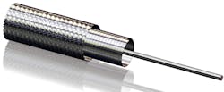
Occasionally, the limit level chosen at the beginning of development seems to be adequate because no issues were detected in the first cables assembled. As more wire is produced, the magnitude of the FFT spikes can vary inside the initial limit from batch to batch. When this happens, VSWR plots from these batches of wire can be compared to FFT plots to determine if a tighter FFT limit should be implemented (Fig. 2).

This may require manufacturing process adjustments, which could have unforeseen consequences on other properties in the wire, and thus in the cable. Collaborative technical dialogue between the wire and cable engineers provides the best opportunity to optimize all production processes involving raw wire and cable materials to achieve the best possible characteristics in the cable.
If an adjustment to the wire process is required, it’s prudent to produce a small sample spool of wire with the proposed changes for testing by the cable maker under engineering supervision. Once the desired results are confirmed, the revised wire specification and the process can be moved into mass production.
Control Mechanical Properties to Aid Micro-bending
Changing mechanical properties also can improve the performance of helical wrap wire. This has less to do with VSWR performance and more to do with how the wire itself handles the wrapping process. The thickness of these wires tends to be on the order of 0.002 in. (0.050 mm) and it’s being wrapped around diameters around the order of 0.020 in. (0.50 mm).
Due to the small order of magnitudes involved, the wrapping of a shield wire around a dielectric could be categorized as a micro-bending process. Micro-bending refers to thin foils being formed around tight radii. The behaviors observed during micro-bending don't follow classic formability laws associated with sheet metals. In this realm, the ratio of grains per unit thickness of foil begins to dictate the material’s behavior during forming. For these reasons, the process of helically wrapping the shielding or wrap wire around the dielectric qualifies as micro-bending.
To achieve the unique microstructure (micro-temper) that’s optimal for the cable, the wire maker needs to develop an appropriate thermal treatment process. The etching of copper grains can sometimes be more of an art than a science, so it’s not a reliable means by which to write a specification. Fortunately, each of these unique microstructures has a unique set of mechanical properties that can be used to easily ensure the heat-treated (annealed) wire has the appropriate micro-temper.
Understanding Micro-tempers for Cable Applications
Many times, specifications determine the temper of a wire by the elongation of the wire. Some cable manufacturers find softer wire better handles their wrapping process, but that elongation alone will not guarantee their success from batch to batch. Cable manufacturers should realize that softness is not the only thing to consider, and other mechanical properties better predict how the material will respond when it’s wrapped.
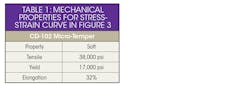
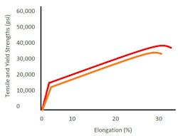
To help show the difference in mechanical properties of different micro-tempers, and how they impact the wire during wrapping, consider the stress-strain curve from a tensile test of pure copper in the “soft” condition and the resulting properties (Figure 3 and Table 1). The elongation is determined by how far the material stretches before it breaks. However, this may not accurately describe the wire's behavior during wrapping because the wire isn’t being pushed to complete failure. Tensile strength describes the stress the material must undergo to reach its maximum elongation at failure, so this also fails to describe the material’s behavior under wrapping tension.
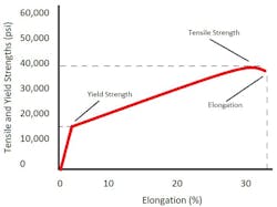
The yield strength, however, occurs at about half of the applied force of the tensile strength and 1% elongation. When the yield strength is crossed during a tensile test, it means that the wire has shifted from elastic to plastic deformation.
Elastic deformation means that enough stress has been applied to the wire to make it slightly elongate, but that it will return to its original length if the stress is relieved. Plastic deformation means that enough stress has been applied for the wire to elongate past the point at which it can return to its original length if the stress is relieved.
Let's imagine a case where the stress applied exceeds the yield strength (stress of 20,000 psi) and the wire plastically deforms. If we find where the stress-strain curve of the “soft” micro-temper reaches 20,000 psi, and look down at the x-axis (Figure 3, again), we see elongation of 10%. Therefore, we know that when 20,000 psi is applied, the wire will elongate from 10 in. in length to 11 in. and will stay at 11 in. when the stress is relieved.
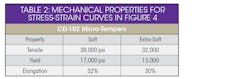
For cable makers struggling to have helical wrap wire that’s soft enough based only on the elongation measurement, an “extra-soft” micro-temper could help (Figure 4 and Table 2). By reducing the yield strength of the wire, the wire will require less tension during wrapping to undergo the same amount of deformation. This does come at a slight cost to the tensile strength and elongation, but that should not be of concern if the wire isn’t pushed to the point of failure.
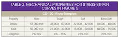
A “tough” micro-temper has a much higher yield strength than is typically found in annealed copper (Figure 5 and Table 3). While the overall tensile strength is slightly higher as well, the nearly 2X normal yield-strength value is what’s truly unique. This means that a stress that would break a standard annealed copper wire won't even permanently deform wires annealed to this micro-temper.
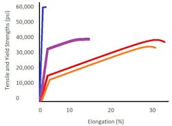
Again, there’s always a give and take when changing mechanical properties, and the “tough” wire usually has around 15% elongation. But we know that high-strength copper alloys used in some cable applications only have around 8% elongation, rendering them soft enough to survive their handling in the machine.
While it doesn't have quite the yield strength of a “soft” high-strength copper alloy, one advantage of the “tough” wire is that because it’s still a pure copper alloy, there’s no conductivity loss. When comparing stress-strain curves as well as properties, you can see that it falls right between the traditional “hard” and “soft” conditions (Figure 5 and Table 3, again).
The “tough” micro-temper could be ideal for applications where increased tension helps with cable performance, yet traditional copper tempers can’t hold up under these tensions.
Work Collaboratively with a Wire Partner
High-performance cable producers would be well-served to partner with a technically competent wire supplier who can help enable the best possible performance in their cables. The wire producer needs to be able to measure and control a variety of subtle variables. These variables, once understood, can be written into specifications that result in performance gains in the assembled cable. When the wire and cable makers work collaboratively, these characteristics are captured so that manufacturing time and purchasing funds aren’t wasted on defective cables.
The wire producer can become an integral part of the cable development team. There’s no one-size-fits-all solution for developing cable wires. Some problems that arise when moving to full-scale production can only be solved by a joint effort between the wire and cable engineers.
About the Author
Leif Kays
New Product Development Engineer, Ulbrich Specialty Wire Products
Leif Kays graduated from Clemson University with a B.S. in Material Science & Engineering in 2016. While a student, he began working with Ulbrich through the Cooperative Education program in 2014, where he first became exposed to the manufacturing of RF cable components. After being hired full time, he has continued to work on this product line while also contributing to development of material characterization techniques.
