Amplifier systems were once associated only with test-and-measurement equipment as a means of boosting low-level test signals. But ready-to-use amplifier systems have gained acceptance for a growing number of applications, including in radar platforms, electronic-warfare (EW) systems, electronic-countermeasure (ECM) systems, and satellite-communications (satcom) networks. Amplifier systems, which may be based on electron tubes, on solid-state transistors, or a combination of the two technologies, are available from a variety of suppliers for both pulsed and continuous-wave (CW) use, in narrowband and broadband models from high-frequency (HF) bands through millimeter-wave frequencies. They often include digital controls to simplify programmability.
In contrast to smaller amplifier modules, which often require additional power-supply and control circuitry, amplifier systems are more self-contained (typically supplied in 19-in.-wide, rack-mount enclosures). Amplifier systems generally include power supplies, allowing the amplifier to be run from a standard alternating-current (AC) power supply or vehicular power supply as needed. They also typically include control circuitry built around a microprocessor and an operating system, and may include enough memory to record events and operating conditions.
One of the best-known names in complete amplifier systems, AR RF/Microwave Instrumentation (www.ar-worldwide.com), supplies a wide range of products based on solid-state electronics, as well as traveling-wave tubes (TWTs) and TWT amplifiers (TWTAs). The firm’s amplifiers, easily recognized by their trademark orange stripe across the front panel, support communications, radar, surveillance and, especially, test-and-measurement applications including in electromagnetic-interference (EMI) and electromagnetic-compatibility (EMC) test systems. In fact, the home page of the company’s website shows charismatic Chairman Donald “Shep” Shepherd standing next to one of the firm’s majestic rack-mount amplifier systems.
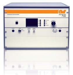
One of the company’s more recent introductions, model 250S1G2z5 (Fig. 1), is an air-cooled, solid-state amplifier system designed to provide at least 250 W output power (when fed with a 1-mW input signal) from 1.0 to 2.5 GHz with high linearity, for testing modern wireless communications systems. It is supplied in its own cabinet for benchtop use, but can be removed for the cabinet for rack-mount installations. It achieves nominally 275 W output power at 3-dB compression and a minimum of 200 W output power at 1-dB compression. The output-power flatness is typically ±1.5 dB. The maximum gain is 54 dB, which can be adjusted over a continuous range of 20 dB.
1.Model 250S1G2z5 is solid-state amplifier system capable of 250 W output power from 1.0 to 2.5 GHz. [Photo courtesy of AR RF/Microwave Instrumentation (www.ar-worldwide.com).]
This amplifier system consumes 1250 W or less power from a 90 to 264 VAC supply. A front panel gain control allows an operator to set the desired output level, which can also be controlled remotely via one of its many digital interfaces. It includes GPIB, RS-232 (via coaxial and fiber-optic connectors), Ethernet, and Universal Serial Bus (USB) ports. The high-linearity amplifier, which includes forced-air cooling by means of self-contained fans, boasts a typical third-order intercept point of +64 dBm and typical noise figure of 10 dB. A front-panel digital display indicates operating status and fault conditions. The amplifier incorporates protective circuitry, which removes DC supply voltage to the amplifier stages if the operating temperature reaches a preset dangerous level. An RF input leveling circuit controls input signal levels to the amplifier system’s first-stage amplifier when the RF input level is boosted beyond 0 dBm.
Of course, transistors have been gaining on TWTs in terms of output power for many years, and transistor-based RF/microwave amplifier systems are readily available with output-power levels that rival the best TWTA systems. For example, model 2066-BBS3K4AUT (Fig. 2) from EMPOWER RF Systems (www.EmpowerRF.com) delivers as much as 1 kW output power from 500 to 1000 MHz using silicon laterally diffused metal-oxide-semiconductor (LDMOS) transistors. Suitable for CW, modulated, and pulsed signals, the system incorporates precision matching networks, as well as switched filter banks and forced-air cooling. It can operate from single-phase or three-phase AC voltage supplies from 180 to 260 VAC.
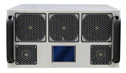
2. Model 2066-BBS3K4AUT is another high-power solid-state amplifier, rated for as much as 1 kW output power from 500 to 1000 MHz using silicon LDMOS transistors. [Photo courtesy of EMPOWER RF Systems (www.EmpowerRF.com).]
The model 2066-BBS3K4AUT is rated for 1000 W saturated output power across its 500-MHz bandwidth, with 800 W output power at 1 dB compression. It is designed to reach its rated output-power levels with a 1-mW (0 dBm) input signal. The rack-mount amplifier features 60-dB gain at 1-dB output power, with a 15-dB gain control range and ±2.5 dB worst-case gain flatness. The amplifier system has a third-order intercept point of +69 dBm and typical noise figure of 10 dB, with low harmonic and spurious signal levels for use in test-and-measurement applications. It uses TTL control for system enable/disable and is fully equipped in terms of remote-control ports, including Ethernet, RS-232, and USB ports. The amplifier, which weighs 90 lbs, does require a robust power supply to achieve its rated output power levels, consuming typically 5000 W power.
The high-power LDMOS amplifier incorporates built-in control and monitoring capabilities, executing remote management and diagnostic functions via an embedded web server for remote status updates and control by connecting the amplifier’s Ethernet port to a local area network (LAN). By using an Internet web browser and the amplifier’s Internet Protocol (IP) address, remote operators are provided with simple access that is backed by multilevel security. The control system core even includes nonvolatile memory for event recording, runs an embedded Linux operating system (OS), and supports hardware encryption for added security.
Some amplifier systems are designed for specific waveforms, such as the model SSPA 0.96-1.22-2000 solid-state amplifier system from Aethercomm (www.aethercomm.com). Supplied as two rack-mountable chassis, the L-band power amplifier system operates from 960 to 1220 MHz with 2000 W typical peak output power and 60-dB typical gain. It is suitable for testing a number of different military waveforms, including tactical air navigation (TACAN) signals, Joint Tactical Information Distribution System (JTIDS) signals, and Link 16 tactical data signals. The amplifier system performs forward and reflected power sampling to monitor operating conditions, and includes an output isolator for protection from mismatched loads and a thermal-management subsystem to protect the components from overheating. The system is designed to operate from 208-VAC three-phase power. One equipment enclosure holds RF amplifiers, monitoring circuitry, and computer interfaces, while the other enclosure contains the AC/DC power-conversion and filtering components.
CTT’s (www.cttinc.com) 19-inch rack-mount amplifiers (Fig. 3) are designed for wideband or narrowband linear applications covering ultra-high frequency (UHF) through Ka-Band (0.5 to 40 GHz). The solid-state amplifier systems are based on a number of different device technologies, including silicon bipolar, gallium arsenide (GaAs) MESFET, and gallium nitride (GaN) FET devices. Cooling fans and heat sinks are included to keep the junction temperature of the transistors in a safe operating region. All units have an EMI/RFI filter, built in regulator and/or sequential bias circuit for protection. Output power monitor, RF connectors, waveguide input or output, alarm circuitry, attenuator or DC/DC converters are optional. These units are ideally suitable for commercial and industrial applications, which need low maintenance, good performance and high reliability. They are most suitable for TWT replacements, driver amplifiers, transmitters, ground stations and point-to-point communication requirements.
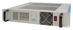
3. Some suppliers offer amplifiers as subassemblies or as complete rack-mount systems targeting different applications. [Photo courtesy of CTT, Inc. (www.cttinc.com).]
A growing trend in microwave power amplifier systems is to include front-panel display screens with status and control information. Model XTRT-400C from Comtech Xicom Technology (www.xicomtech.com) is an amplifier system designed for fixed and mobile satcom uplink applications from 5.850 to 6.425. It combines a TWTA output stage with a solid-state preamplifier; also included are RF gain control, a solid-state preamplifier, RF filters, cooling, and monitoring and control subsystems, all within a three-unit-high 19-in. rack-mount enclosure (Fig. 4). The TWT is rated for 400 W output power while the amplifier system is rated for 350 W minimum power at its output flange. Power factor correction circuitry is also included to minimize line current distortion.
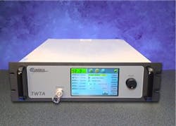
4. Model XTRT-400C combines a solid-state preamplifier with a TWTA output stage and microprocessor control, within a 3U high rack-mount enclosure. [Photo courtesy of Comtech Xicom Technology (www.xicomtech.com).]
The display shows HPA status, parameter trend analysis, and event logs. Remote diagnostics can be performed by means of a built-in Ethernet interface. The display can also show and control additional components, such as waveguide switches and power combiners, to eliminate the need for additional controllers at the system level. The TWTA-based system features minimum large-signal gain of 70 dB and minimum small-signal gain of 75 dB from 5.850 to 6.425 GHz, with a continuous attenuation range of 25 dB. Small-signal-gain variations are controlled to 1 dB per 40 MHz of bandwidth and 2.5 dB for 575 MHz of bandwidth, with gain stability within ±0.25 dB for a 24-h period.
Applied Systems Engineering (www.applsys.com) builds pulsed klystron tube amplifiers, such as the model 445. It delivers 27 kW pulsed output power from 7.9 to 8.4 GHz, operating across a 50-MHz bandwidth with a 9% duty cycle and pulse repetition frequency (PRF) of 100 kHz. It works with pulse widths from 0.1 to 100.0 μs. The company also supplies CW klystron amplifiers, such as the model 597, with 1.5 kW output power across a 20-MHz bandwidth from 6.95 to 7.00 GHz.
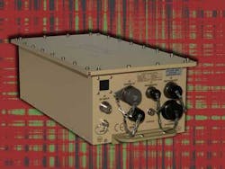
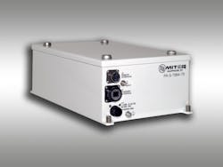
MCL, Inc. (www.mcl.com), a MITEQ (www.miteq.com) company, recently introduced its model MT2100 TWTA-based power amplifier for outdoor, airborne applications requiring at least 100 W broadband output power from 6 to 18 GHz. The compact design weighs just 25 lbs (Fig. 5) and uses conduction cooling, although forced-air-cooled and liquid-cooled versions are available. MITEQ itself is perhaps best known for its satcom amplifier systems, such as model PA-S-7984-70 for use from 7.9 to 8.4 GHz (Fig. 6). In contrast to MCL’s model MT2100, this is a solid-state amplifier with 35 W output power and 70-dB small-signal gain with excellent gain flatness. It is designed for outdoor use, mounted on an antenna mast, and weighs only 20 lbs (9.1 kg) and measures 13.7 x 5.1 x 7.75 in. As with many of the firm’s amplifier systems, it can be supplied with an integrated frequency block upconverter (BUC) that accepts L-band intermediate-frequency (IF) signals from 950 to 1450 MHz. The weatherproof package weighs just 20 lbs (9.1 kg).
5. Designed for outdoor and airborne use, model MT2100 is an amplifier system based on TWTs, for use from 6 to 18 GHz. [Photo courtesy of MCL (www.mcl.com).]
6. Model PA-S-7984-70 is a satcom amplifier for use from 7.9 to 8.4 GHz. [Photo courtesy of MITEQ (www.miteq.com).]
For test purposes, broad bandwidth is critical. The model GT-1051A power amplifier (Fig. 7) from Giga-tronics (www.gigatronics.com) may lack the power levels of some of the other “power” amplifiers, with a rating of 0.25 W (+24 dBm) output power, but it is extremely broadband, from 10 MHz to 50 GHz. It achieves gain flatness of ±5 dB across that bandwidth and is based on reliable, solid-state technology. The company also offers its model GT-1000A rack-mountable power amplifier based on the firm’s Spatium™ technology with GaAs MMIC amplifiers. It generates 10 W output power from 2 to 20 GHz and a 14-dB noise figure. Intended as a TWTA replacement, it boasts -30 dBc harmonics and -60 dBc spurious levels.
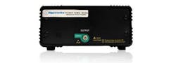
7. Model GT-1051A is not truly a power amplifier, but is it broadband, with a range of 10 MHz to 50 GHz. [Photo courtesy of Giga-tronics (www.gigatronics.com).]
These amplifiers are just a sampling of the “ready-to-use” amplifier systems available on the market. Additional suppliers include Aethercomm (www.aethercomm.com), Auriga Microwave (www.aurigamicrowave.com), EMPower RF Systems (www.EmpowerRF.com), e2v aerospace and defense inc. (www.e2v-us.com), OPHIR RF (www.ophir.com), SpectraDynamics, Inc. (www.spectradynamics.com), and Wright Technologies, Inc. (www.wrighttec.com). Many more are listed in Microwaves & RF’s Product Data Directory (www.mwrfpdd.com).
About the Author
Jack Browne
Technical Contributor
Jack Browne, Technical Contributor, has worked in technical publishing for over 30 years. He managed the content and production of three technical journals while at the American Institute of Physics, including Medical Physics and the Journal of Vacuum Science & Technology. He has been a Publisher and Editor for Penton Media, started the firm’s Wireless Symposium & Exhibition trade show in 1993, and currently serves as Technical Contributor for that company's Microwaves & RF magazine. Browne, who holds a BS in Mathematics from City College of New York and BA degrees in English and Philosophy from Fordham University, is a member of the IEEE.
