Balance Microwave LPF Responses with CSRRs

Download this article in PDF format.
Also recognized as co-author is Bouazza Tayeb Habib Chawki, a Ph.D. Candidate in the LTC Laboratory, Department of Electronics, Faculty of Technology, University Dr. Moulay Tahar of Saida.
Resonant structures capable of metamaterial behavior can be quite beneficial when it comes to microwave filter designs. In particular, split-ring resonators (SRRs) and complementary SRRs (CSRRs) were found to enhance the performance of a conventional stepped-impedance microstrip lowpass filter (LPF) when etched into the filter’s ground plane. The metamaterial-like properties of CSRRs include the capabilities to achieve negative relative permeability and permittivity within the rejection band of the LPF while providing low insertion loss in the filter passband.
To explore the potential of SRRs and CSRRs in filter design, a conventional microstrip-based LPF was designed and simulated with the aid of a commercial electromagnetic (EM) simulator. Then variations were made with the addition of the CSRRs to understand their effects on performance. Filters were fabricated on commercial printed-circuit-board (PCB) material to validate the results of the simulation.
For electromagnetic (EM) applications, metamaterials refer to composite materials with EM properties that are not naturally occurring. Metamaterials typically feature periodic dielectric or metallic structures that act as homogeneous materials. These types of materials were first discovered by Veselago in 1968.1 Thirty years later, the properties were verified experimentally by Pendry.2,3 One year later, Smith and associates demonstrated a split ring resonator (SRR) using a left-handed metamaterial obtained by combining two periodic and homogeneous materials.4,5 It was capable of producing negative values of effective permeability and effective permittivity for metamaterials with negative refractive index.6,7
Some years later, Caloz and Itoh proposed another method to produce left-handed metamaterials by using a transmission-line format based on microstrip technology.8,9 Of the many EM metamaterial-type structures currently available, most are based on the SRR concept. These are resonators with magnetic responses well suited for microwave applications, including waveguide transmission lines, filters, and antennas.10,11
Exploring the SRR Effect on HF Filters
To understand the impact of different types of SRRs on high-frequency filter circuits, a stepped-impedance LPF was designed in microstrip with a cutoff frequency of 5.5 GHz. CSRRs were etched into the ground planes of the LPF to explore their metamaterial properties. The CSRRs contributed to low passband insertion loss and flat passband amplitude response, with improved filter rolloff characteristics. The effects were studied by means of computer simulations, using the HFSS finite-element EM simulation software from ANSYS.

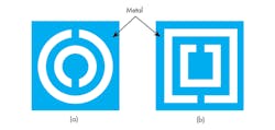
1. These sketches show (a) circular and (b) square layouts for split-ring resonators (SRRs).
SRRs were among the first resonant structures proposed for metamaterial construction purposes. Metallic metamaterials formed of double SRRs achieve magnetic responses at microwave frequencies. For example, the SRR structures shown in Figure 1 have been used to obtain a negative value of effective permeability over a desired frequency range. Negative permeability can prevent wave propagation at a resonant frequency.12
A CSRR structure is achieved by doubling the number of SRRs in the ground plane in different shapes, to create double split rings and structures having apertures in metal surfaces (such as a microstrip ground plane).13 Some examples of CSRRs with different shapes are shown in Figure 2.
2. These layouts represent two different kinds of complementary SRRs (CSRRs): (a) circular CSRRs and (b) square CSRRs.
Extracting the effective parameters of the SRRs and CSRRs needed to achieve a particular filter response known as the Nicolson-Ross-Weir (NRW) method.14 The values of the required EM parameters are determined according to a homogenization theory and extracted from reflection and transmission coefficients, such as scattering (S) parameters.
The purpose of the homogenization theory is to describe in a simple way, but with microscopic detail, the response of a structure such as a CSRR to incident EM radiation. The basic idea involved modeling a metamaterial structure as a homogeneous, isotropic slab, calculating the effective parameters ε and μ of the homogeneous slab from the transmission and reflection coefficients obtained by simulations using MATLAB mathematics-based software from MathWorks.
For an isotropic homogeneous slab in a vacuum, transmission (t) and reflection (r) have the following relationships with the refractive index (n) and the impedance (z) of the slab15:
t-1 = {cos(nkd) – (i/2)[z + (1/z)] sin(nkd)} (1)
r/t = {–(i/2)[z – (1/z)]sin(nkd)} (2)
where k and d are the wave vector and thickness of the slab, respectively. By inverting Eqs. 1 and 2, n and z can be calculated from t and r. Performing the inversions results in (Eqs. 3 and 4):
z = ±{ [(1 + r)2 – t2]/[(1 – r)2 – t2]}0.5 (3)
cos(nkd) = (1/2t)(1 + t2 – r2) (4)
By using the Sij scattering parameters, the effective material parameters can be extracted16:
z = ±{[(1 + S11)2 – S212]/[(1 – S11)2 – S212]}0.5 (5)
Re(n) = ±Re({cos-1[1/2S21(1 – S112 + S212)]}/kd) (6)
Im(n) = ±Im({cos-1[1/2S21(1 – S112 + S212)]}/kd) (7)
The ambiguity of the signs (±) for Eqs. 5, 6, and 7 can be avoided by noting that the real part of the impedance is positive if it is for a passive medium, while the imaginary part of the refractive index is positive to ensure that the amplitude of the incident wave decreases inside the structure. The effective permittivity and permeability can be computed by using Eqs. 8 and 9:
ε = n/z (8)
μ = nz (9)
Microstrip LPF Design
Figure 3a shows the general structure of a conventional stepped-impedance microstrip LPF. It employs a cascaded structure of alternating high- and low-impedance transmission lines. The high-impedance lines act as series inductors and the low-impedance lines behave as shunt capacitors in the filter circuit. Figure 3b shows the equivalent-circuit representation of the LPF structure.17
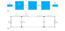
3. The (a) basic structure and (b) equivalent-circuit representation of a stepped-impedance microstrip LPF are shown here.
For the stepped-impedance design prototype, a third-order (n = 3) Chebyshev response was chosen, with prototype circuit-element values given by:
g0 = 1
g1 = 1.0316
g2 = 1.1474
g3 = 1.0316
g4 = 1
For the normalized cutoff impedance, Ωc = 1, the element transformations in ref. 17 were used to find the values of inductors and capacitors for the filter by applying Eqs. 10 and 11:
L1 = L3 = (Z0/g0)(Ωc/2πfc)g1 = 1.492 × 10⁻⁹ H (10)
C2 = (g0/Z0)(Ωc/2πfc)g2 = 0.664 × 10⁻¹² F (11)
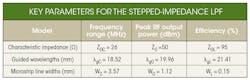
The filters were implemented on circuit-board material with relative dielectric constant (εr) of 10.2 and a substrate height (h) of 1.27 mm. The characteristic impedances (Z0) of the high- and low-impedance lines, L and C, respectively, were chosen as 95 and 26 Ω, respectively, by controlling the widths (W) of the microstrip transmission lines for the target frequency range. The relevant design parameters of microstrip lines, which were determined using the formulas in ref. 17, are listed in the table.
The physical lengths of the high- and low-impedance lines may be found by using Eqs. 12 and 13:
lL = (λgL/2π)sin-1(ωCL/Z0L) (12)
lC = (λgC/2π)sin-1(ωCCZ0C) (13)
where L and C represent the circuit-element values for the lumped inductors and capacitors, respectively. The equations result in lL of 1.95 mm and lC of 1.88 mm. The results do not take into account the series reactance of the low-impedance line and shunt susceptance of the high-impedance lines. To include these effects, the lengths of the high- and low-impedance lines should be adjusted to satisfy the following relationships:
ωCL = Z0Lsin(2πlL/λgL) + Z0Ctan(πlC/λgC)
ωCC = (1/Z0L)sin(2πlC/λgC) + 2(1/Z0L)tan(πlL/λgL)
By solving this set of equations for lL and lC, the results are 1.59 mm and 1.32 mm, respectively. Figure 4 shows a layout of the microstrip filter designed with these circuit-element values. Figure 5 shows the simulated transmission (S21) and reflection (S11) coefficients as determined by HFSS.
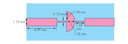
4. This is the layout of the microstrip LPF configured according to the design equations for a high-dielectric-constant (10.2) circuit substrate.
5. The simulated S21 and S11 responses for the microstrip LPF are plotted in this illustration.
A CSRR is a dual counterpart of an SRR, with dual EM behavior expected according to the duality theorem. The incident electric field must be polarized in the axial direction of the resonator. In this way, CSRRs are etched on center line of a microstrip transmission line layout.18 This ensures that the CSRRs are properly excited by the electric field applied parallel to the ring axis. Since CSRRs are excited by the electric field, they produce negative effective permittivity, or Re(εeff) < 0. Figure 6 shows the CSRR topology and equivalent-circuit model.
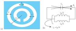
6. The layout (a) depicts a CSRR with its relevant dimensions, with (b) an equivalent circuit for a CSRR-loaded microstrip line.
The CSRR unit cell was designed to operate around 7 GHz. The geometry of the cell is as follows: c = d = 0.3 mm; g = 0.3 mm; and m = 3 mm. It was fabricated on RO3210C circuit material from Rogers Corp. with relative permittivity (εr) of 10.8, loss tangent (tan δ) of 0.0019, and thickness (h) of 1.27 mm. The CSRR was simulated by HFSS.
The CSRR can be described as an LC resonant circuit. The resonant frequency, f, is described by the following expression18:
f = 1/[2π(LCCC)0.5] (14)
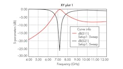
7. The Sij parameters for the CSRR were simulated with HFSS finite-element EM simulation software.
Figure 7 shows the Sij parameters for the simulated results. The frequency-rejection band occurs around the design frequency, at 7.1 GHz, with transmission loss of about 26 dB. Figure 8 shows that the real part of the permittivity exhibits Lorenzian response behavior, with negative value in the frequency range between 5.5 and 6.13 GHz.
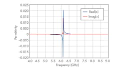
8. These plots show the real and imaginary parts of the permittivity.
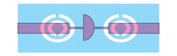
9. This layout depicts a microstrip LPF loaded with two CSRRs.
To achieve good electrical performance for the filters, the design parameters were tuned and optimized using HFSS. Figure 9 shows the two cells of circular CSRRs etched into the microstrip ground plane. The geometric parameters a = b as well as c are 3 mm and 0.3 mm, respectively. The gap between the inner and outer etched forms is 0.3 mm, and each of the splits in the inner and outer rings has the same width of 0.3 mm. Figure 10 shows simulation results for the microstrip LPF using Ansoft Design from ANSYS. As can be seen, the response is on the order of ‒20 dB for the frequency range below 6.25 GHz.
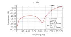
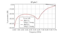
10. The S21 and S11 responses for the two-CSRR-loaded filter were simulated with HFSS.
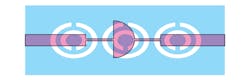
11. This layout represents a microstrip LPF loaded with three CSRRs.
Figure 11 depicts the microstrip filter with three circular CSRRs etched into the ground plane. The resonators, which are etched into the high-impedance transmission lines, have 0.2-mm spacing between them. Figure 12 shows the effects of the CSRRs on the filter’s performance, with a frequency response of about –15 dB below 6.25 GHz. The frequency band for the negative refractive index lies approximately between 2.4 and 5.31 GHz. This is the frequency range in which the permittivity and the permeability are simultaneously negative (Fig. 13).
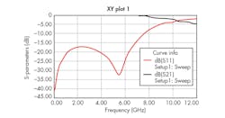
12. These are the simulated S21 and S11 responses for the three-CSRR-loaded filter.
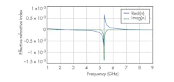
13. The plots show the real and imaginary values for the effective refractive index as impacted by the CSRRs.
In summary, the design efforts started with a conventional stepped-impedance LPF with cutoff frequency of 5.5 GHz. By loading it with CSRRs, a negative refractive index was achieved. Loading can be accomplished by etching circular CSRRs in the ground plane of microstrip LPF circuits. The result is a CSRR-loaded LPF with low passband insertion loss and good cutoff response. Adding resonators can increase the frequency band, with some degradation in passband response.
References:
1. V. G. Veselago, “Electrodynamics of substances with simultaneously negative electrical and magnetic properties,” Soviet Physics, Vol. 10, 1968, pp 509-517.
2. J. B. Pendry, A. J. Holden, W. J. Stewart, and I. Youngs, “Extremely low frequency plasmons in metallic mesostructures,” Physical Review Letters, Vol. 76, 1996, pp. 4773-4776.
3. J. B. Pendry, A. J. Holden, D. J. Ribbins, and W.J. Stewart, “Magnetism from conductors and enhanced nonlinear phenomena,” IEEE Transactions on Microwave Theory & Techniques, Vol. 47, November 1999, pp. 2075-2084.
4. D. R. Smith et al., “Composite Medium with Simultaneously Negative Permeability and Permittivity,” Physical Review Letters, Vol, 84, May 2000, p. 4184.
5. R. A. Shelby, D. R. Smith, and S. Shultz, “Experimental verification of a negative index of refraction,” Science, Vol. 292, April 2001, pp. 77-79.
6. D. R. Smith, “The reality of negative refraction,” Physics World, Vol. 16, 2003, pp. 23–24.
7. D. R. Smith, J. B. Pendry, and M. C. K. Wiltshire, “Metamaterials and negative refractive index,” Science, Vol. 305, 2004, pp. 788–792.
8. S. Atsushi; C. Caloz, and T. Itoh, “Characteristics of the Composite Right/Left-Handed Transmission lines,” IEEE Microwave and Wireless Components Letters, Vol. 14, No. 2, February 2004, pp. 68-70.
9. C. Caloz and T. Itoh, Electromagnetic Metamaterials: Transmission Line Theory and Microwave Applications, Wiley, New York, 2006.
10. M. Gupta, J. Saxena, “Microstrip Filter Design by SRR Metamaterial,” Wireless Personal Communications, Vol. 71, No. 4, August 2013, pp 3011-3022.
11. S. Naoui, L. Latrach, and A. Gharsallah, “Metamaterials dipole antenna by using split ring resonators for RFID technology,” Microwave & Optical Technology Letters, Vol. 56, 2014, pp. 2899-2903.
12. Ho Lim, Jong-Hyuk Lee, Sang-Ho Lim, Dong-Wook Seo, Dong-Hoon Shin, and Noh-Hoon Myung, “A Novel Compact Coplanar Waveguide Bandstop Filter Based on Split ring Resonators,” Proceedings of ISAP2007, Niigata, Japan, 2007.
13. W. H. Hayt and J. A. Buck, Engineering Electromagnetics, 6th ed., McGraw-Hill, New York, 2001.
14. A. M. Nicolson and G. F. Ross, “Measurement of the intrinsic properties of materials by Time-Domain techniques,” IEEE Transactions on Instrumentation and Measurement, Vol. 19, No. 4, 1970, pp. 377–382.
15. D. R. Smith, S. Schultz , P.Markos, and C.M.Soukoulis, “Determination of effective permittivity and permeability of metamaterials from reflection and transmission coefficients,” Physical Review, Vol. 65, 2002, p. 195.
16. C. Sabah, “Tunable metamaterial design composed of triangular split ring resonator and wire strip for S and C microwave bands,” Progress in Electromagnetics Research B, Vol. 22, 2010.
17. Jia-Sheng and M. J. Lancaster, Microstrip Filters for RF/Microwave Applications, Wiley, New York, 2001.
18. F. Falcone, T. Lopetegi, J. D. Baena, R. Marqués, F. Martín, and M. Sorolla, “Effective Negative Epsilon Stop-Band Microstrip Lines Based on Complementary Split Ring Resonators,” IEEE Microwave and Wireless Components Letters, Vol. 14, June 2004, pp. 280-282.

About the Author
Becharef Kada
Ph.D. Candidate
Becharef Kada is a Ph.D. candidate in the LTC Laboratory, Department of Electronics, Faculty of Technology, University Dr. Moulay Tahar of Saida.
Nouri Keltouma
Associate Professor
Nouri Keltouma is an Associate Professor at LTC Laboratory, Department of Electronics, Faculty of Technology, University Dr. Moulay Tahar of Saida.
Bouazza Boubakar Seddik
Associate Professor
Bouazza Boubakar Seddik is an Associate Professor at LTC Laboratory, Department of Electronics, Faculty of Technology, University Dr. Moulay Tahar of Saida.
Damou Mehdi
Ph.D. Candidate
Damou Mehdi is a Ph.D. candidate at LTC Laboratory, Department of Electronics, Faculty of Technology, University Dr. Moulay Tahar of Saida.
