Amplifier Powers an Octave with 80% Average Efficiency
Download this article as a .PDF
Efficiency is one of the most sought-after parameters in RF power amplifier (PA) design, since it translates directly to power consumption and operating cost. In continuous inverse Class F (CCF−1) PAs, the current waveform factor, δ, plays a major role in achieving high drain efficiency. With a modified lowpass output matching network (OMN), it is possible to constrain δ to a limited range high drain efficiency even when operating a PA with broadband frequency coverage. The approach was demonstrated in a an easy-to-implement PA design that operates from 1.0 to 1.9 GHz (a fractional bandwidth of 62%) that achieves +39.8 to +42.0 dBm output power across the frequency band with drain efficiency of 75.8 to 84.5% (average drain efficiency of 80%).
High-efficiency PAs are important components in modern communications systems, particularly when broadband frequency coverage and high-data-rate performance are required.1 Classic harmonic tuned PAs, such as Class E amplifiers or those operating in Class F mode2 or inverted Class F (F−1) mode typically operate with high efficiency but limited bandwidths. To extend the bandwidth of high-efficiency amplifiers, a continuous working mode was proposed by Steve Cripps in 2009, with additional concepts introduced more recently, including Class B/F mode,3 continuous Class F mode,4 and continuous Class F−1 mode.5
These continuous working modes require that second-harmonic loads are tuned to the edge of the Smith chart, which is an almost impossible condition to meet across a broad frequency range. The extended continuous class F−1 mode6 is derived through managing the current waveform of classic continuous Class F−1 mode by adding a cosine term with a current waveform factor, δ. Waveform factor δ introduces a resistive part to the second-harmonic admittance, easing the requirements for strict impedance loads and, in the process, resulting in a more flexible design space.
Current waveform factor δ plays a critical role in the efficiency of extended CCF−1 mode PAs. The key point of designing an extended CCF−1 mode PA is to design an output matching network (OMN) which allows the use of δ constrained to a small range within the operating frequency band. Simulations with commercial computer-aided-engineering (CAE) software indicate that if the proposed OMN allows δ to be maintained within a range of 0 < δ < 0.26 across an operating frequency range of 1.0 to 1.9 GHz, the corresponding drain efficiency will be higher than 75%. This proposed OMN is relatively simple and easy to assemble.
Designing an Amplifier
The extended CCF−1 PA can be derived by managing the current waveform of classical CCF−1 PAs. It has a half-wave rectified sinusoidal voltage waveform at its intrinsic current-generator (I-gen) plane similar to CCF−1 modes, while its current waveform represents a new family of current waveforms with waveform factor δ varying between 0 and 1. The drain-source current (ids) and voltage (Vds) waveform expressions are as follows:
ids (θ) = (0.37 – 0.43cosθ + 0.06cos3θ)(1 – γsinθ)(1 + δcosθ) (1)
where −1 ≤ γ ≤ 1
and
Vds (θ) = 1 + [2/(2)0.5](cosθ) + 0.5cos2θ (2)
Building upon these expressions, the output fundamental and harmonic admittances for the extended CCF−1 mode can be found by means of Eqs. 3, 4, and 5, where Gopt represents the optimal admittance for the PA’s transistors:
Y1f = (2)0.5[(1.16 – δ) – j(0.33δγ – γ)(Gopt)] (3)
Y2f = −2[ −δ + j(1.32 – δ)γ]Gopt (4)
Y3f = ∞ (5)
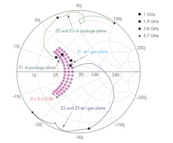
Figure 1 depicts the fundamental, second, and third harmonic admittances of the extended CCF−1 modes. As can be seen from the Smith chart, δ = 0 corresponds to the classical CCF−1 mode. The fundamental load is on the constant susceptance circle, the second-harmonic load varies on the edge of the Smith chart, and the third-harmonic load is fixed at the short-circuit condition. Satisfying all three harmonic load conditions in a broadband PA design is difficult, usually leading to degraded performance in terms of efficiency and output power.
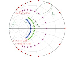
The extended CCF−1 mode occurs when 0 < δ < 1. With variations of current waveform factor δ, the optimal fundamental and second-harmonic loads are moving in opposite directions on the Smith chart. The second-harmonic load is located inside the Smith chart, which represents a resistive part to the second-harmonic admittance. This resistive part extends the design space with a slight sacrifice in efficiency and output power.
The drain efficiency of the extended CCF−1 mode, ηD, can be calculated using Eq. 6:
ηD = [(2)0.5 (1.16 – δ)]/(2 – 1.16δ) (6)
As Eq. 6 shows, ηD is a function of the current waveform factor δ. For a given predetermined minimum targeted efficiency ηD, the corresponding waveform factor δ and impedance space on the Smith chart can be easily calculated. For an enlarged impedance space and range of δ, a specific matching network must be designed. Equation 6 shows that ηD higher than 75% can be achieved when 0 < δ < 0.26, while ηD higher than 70% corresponds to 0 < δ < 0.4.
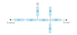
Figure 2 shows a proposed OMN topology based on multiple-section microstrip transmission lines. The serial transmission lines (Z1, Z2, Z3, and Z4) act as inductances, while the shunt transmission lines (Z5, Z6, and Z7) act as capacitances. The combination of serial inductances and shunt capacitances form a five-stage lowpass filter network, which can provide optimal higher-order harmonic suppression. The use of symmetrical shunt open-circuit stubs (Z6 and Z7) helps achieve better broadband performance.
This proposed OMN circuitry can allow fundamental and harmonic loads varying more slowly over frequency on the Smith chart, which is beneficial for constraining current waveform factor δ within smaller range in broadband applications. The modified OMN is suitable for the design of extended CCF−1 mode PAs, and it is simple and easy to implement. Figure 3 shows a complete schematic diagram of the OMN circuitry with dimensions for the transmission lines.
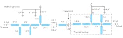
Figure 4 presents the simulated fundamental and harmonic impedance trajectories of the proposed OMN over frequency at both the package plane and the I-gen plane. As can be seen, the fundamental impedance load is located inside the region of 0 < δ < 0.26 as expected, while the second- and third-harmonic loads are located around the optimal region. Indeed, it is important to highlight that when the fundamental load is matched, the mismatching of the second- and third-harmonic loads causes only minimal degradation in efficiency and output power according to a load-pull simulation.7 From the previous theoretical analysis, the drain efficiency ηD of this design has been calculated as exceeding 75% from 1.0 to 1.9 GHz.
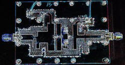
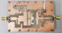
To validate this design approach for the high-efficiency OMN, a broadband PA was designed and assembled based on a model CGH40010F GaN high-electron-mobility-transistor (HEMT) from Cree/Wolfspeed. The transistor is designed to provide as much as 10 W output power from a +28-V dc supply, from DC to 6 GHz. It is available in screw-down flange and solder-down pill-type packages. For the PA printed-circuit-board (PCB) material, rf-35 from Taconic was selected, with board thickness of 30 mil, copper thickness of 35 μm, and relative dielectric constant, εr, of 3.5 in the z axis (thickness) of the material. The assembled prototype PA is shown in Fig. 5.
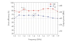
The prototype PA was tested with a gate bias of −2.7 V dc and drain bias set at 28V dc, yielding a quiescent current of 68 mA. The test signal input power to the PA was fixed at +28 dBm. Figure 6 presents the results of the measurements. The PA’s drain efficiency ranged from 75.8% to 84.5% while the output power ranged from +39.8 to +42.0 dBm across an operating frequency range of 1.0 to 1.9 GHz (a fractional bandwidth of 62%). The table lists the comparison between these results and several published designs. All were based on the Cree CGH40010F GaN HEMT. Higher efficiency with equivalent output power and fractional bandwidth were achieved with the current OMN design.

Acknowledgments
This work was supported by the National Natural Science Foundation of China under grant No. 61001012, Teaching Research Project of Huazhong University of Science and Technology (15027), and the Fundamental Research Funds for the Central Universities HUST, No. 2016YXMS207.
Lamin Zhan, Associate Professor
Zhong Xi, Master’s Degree Candidate
Yanghua Li, Master’s Degree Candidate
Wenguang Li, Engineer
Huazhong University of Science and Technology, 1037 Luoyu Rd., Hongshan District, Wuhan, Hubei, 430074, China
References
1. W. Shi, S. He, and Q. Li, “A Series of Inverse Continuous Modes for Designing Broadband Power Amplifiers,” IEEE Microwave and Wireless Components Letters, Vol. 26, No. 7, July 2016, pp. 525-527.
2. K. Chen and D. Peroulis, “Design of Highly Efficient Broadband Class-E Power Amplifier Using Synthesized Low-Pass Matching Networks,” IEEE Transactions on Microwave Theory and Techniques, Vol. 59, No. 12, December 2011, pp. 3,162-3,173.
3. Zhenyang Wang, Guang Yang, and Falin Liu, “An easily implementable structure for broadband high efficiency Class-J power amplifier,” 2014 IEEE Workshop on Electronics, Computers, and Applications, pp. 786-790, 2014.
4. T. Sharma, R. Darraji, and F. Ghannouchi, “Design methodology of high efficiency continuous mode transfer power amplifiers with one octave bandwidth,” 2014 21st IEEE International Conference on Electronics, Circuits, and Systems (ICECS), pp. 674-677.
5. M. Yang, J. Xia, Y. Guo, and A. Zhu, “Highly Efficient Broadband Continuous Inverse Class-F Power Amplifier Design Using Modified Elliptic Low-Pass Filtering Matching Network,” IEEE Transactions on Microwave Theory and Techniques, Vol. 64, No. 5, May 2016, pp. 1,515-1,525.
6. V. Carrubba, et al., “The Continuous Inverse Class-F Mode With Resistive Second-Harmonic Impedance,” Transactions on Microwave Theory and Techniques, Vol. 60, Vo. 6, June 2012, pp. 1,928-1,936.
7. Qirong Li, Songbai He, Zhijiang Dai, and Weimin Shi, “A method for designing generalized continuous power amplifier,” 2016 IEEE MTT-S International Microwave Workshop Series on Advanced Materials and Processes for RF and THz Applications (IMWS-AMP), pp. 1-3.

