Modulation Distortion: An Innovative Method for High-Accuracy EVM Measurements
Download this article in PDF format.
In wireless communication systems, power amplifiers (PAs) make a significant contribution to the quality attained in the RF chain. These components play a critical role in determining the condition of the communication service in terms of signal quality and battery life.
PAs are positioned in the last stage of the transmission chain and generate the RF power that’s then transmitted over the antennas. PA designers aim to maximize linearity while maintaining a high level of efficiency. This balance is challenging to achieve across extremely wide signal bandwidths in the millimeter-wave (mmWave) frequency spectrum.
To measure the nonlinearity of a PA under a modulated stimulus condition, the industry uses error vector magnitude (EVM) as a figure of merit (FOM) for in-band characteristics and adjacent channel power ratio (ACPR) for out-of-band characteristics. This article introduces an innovative method called modulation distortion (MOD) for characterizing the nonlinearity of a PA under modulated stimulus conditions.
Challenges in Device Characterization Under Wideband Modulated Signals
The introduction of 5G new radio (NR) means that designers need to perform EVM measurements using extremely wide signal bandwidths in the mmWave spectrum. A vector signal generator (VSG) combined with a vector signal analyzer (VSA) are traditionally used to measure EVM. However, it’s challenging to measure EVM with these test instruments due to several reasons:
Errors contributed by the stimulus
In the VSA method, the error vector is the value obtained when comparing the ideal signal with the measured signal for each constellation. The integrity of the signal source has a direct impact on the measurement result. The distortion of the generated signal needs to be lower than the distortion generated by the device under test (DUT).
The VSA method is also sensitive to I/Q imbalance and phase noise not normally created by the DUT. In addition, the signal-to-noise ratio (SNR) decreases as the bandwidth (BW) of the signal gets wider and generates noise. Random noise at low power levels can result in less accurate and reliable EVM measurements.
Errors contributed by the receiver
To minimize any errors in the EVM measurement result, the input signal needs to be digitized using a signal analyzer that does not produce any nonlinear distortion. Furthermore, the noise floor of the receiver must be lower than the target signal. This is especially challenging to accomplish across wider signal BWs since the SNR of the receiver is also lower.
To manage the input level of the receiver chain, the attenuation and gain settings of a receiver chain need to be carefully controlled, which requires deep knowledge of the analyzer. Iterating across different input levels and settings to optimize receiver optimization slows down the measurement process.
Signal fidelity
In the VSA method, there are multiple ways to calibrate the test system. The most advanced technique compensates for the I/Q waveform so that the input signal is a flat response at the reference plane. This method may include an error, especially when the test signal has a wide BW and the DUT has poor mismatch.
MOD on a PNA-X VNA
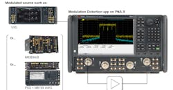
Modulation distortion offers a new approach to overcome the measurement challenges associated with the VSA method. By combining the following PNA-X, VSG, and MOD application, users can characterize the nonlinear distortion of a device under a modulated signal and establish FOMs, including EVM and ACPR (Fig. 1).
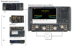
1. MOD is a software application that runs on the PNA-X. It provides an innovative approach for performing device characterization under wideband modulated signals.
Since the entire measurement setup is integrated into the PNA-X firmware, the user can easily configure the stimulus and establish the measurements. Also, the measurement leverages state-of-the-art calibration techniques for optimum accuracy.
On top of that, the MOD application enables users to access additional measurements besides the typical PNA-X measurements, such as S-parameters, gain compression, intermodulation distortion (IMD), and noise figure. The MOD application on the PNA-X also supports nonlinear distortion measurements under a modulated stimulus condition without the need to change the connection.
PNA-X Unique Implementation
Figure 2 shows the block diagram of the measurement system consisting of a PNA-X and a VSG:
- The output of the VSG is connected to the rear panel of the PNA-X (J10) so that the signal can go through the internal path of the PNA-X.
- The modulated signal is then made available from test port 1 (connected to the DUT) of the PNA-X.
- Test port 2 of the PNA-X is connected to the output of the DUT.
- Input and output spectrum of the modulated signal use receivers R1, A, and B, coherently.
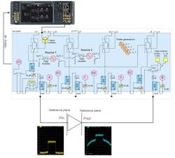
2. This is a block diagram of the measurement system consisting of a PNA-X and a VSG.
All of the required configurations to make a measurement can be completed with the MOD software application integrated into the firmware of the PNA-X. Similar to other application software that runs on a PNA-X, measurements start by creating a channel. The channel contains all of the stimulus-response information as well as the calibration information required for the measurement.
The calibration of the measurement system plays a critical role when making an accurate measurement. The MOD method offers two different types of calibrations to accurately perform EVM and ACPR measurements:
- A linear calibration plane is first established to remove the linear error from the raw measurement result. This can be achieved by the same process as the other measurement class of PNA-X.
- The modulated source correction is then performed to generate the desired modulated waveform at the reference plane.
After the MOD application measures the vector-corrected input and output spectrum with a corrected receiver and the desired modulated waveform, the MOD application processes the data by comparing the input spectrum and output spectrum. The technique is called spectral correlation. With this advanced data processing approach, the MOD decomposes the spectrum into a linearly correlated part and a distortion part. Subsequently, the MOD application computes the FOM such as EVM and ACPR. The correlation of the FOM to the traditional VSA method is mathematically proven, along with actual measurements of the PA.
New Method for Characterizing PA Nonlinear Distortion
Device characterization under wideband modulated signals is a significant challenge. 5G requires PA designers to perform EVM measurements using extremely wide signal bandwidth in the mmWave spectrum. The traditional method using a VSA and VSG is no longer enough. Design engineers need a new method to measure critical parameters for PAs such as EVM and ACPR. The PNA-X MOD application provides various benefits to PA characterization, including:
- MOD overcomes wideband measurement challenges. The wide dynamic range of the PNA-X enables low residual EVM due to wider system dynamic range (lower noise floor). Also, easy calibration for “vector-corrected” measurements enables signal fidelity at the DUT input. As a result, measurement reproducibility improves significantly.
- Design flow improvement with simulation. The same computation engine as the PNA-X to simulate nonlinear behavior is available in the Keysight ADS simulation environment. This enables PA designers to accelerate the design cycle.
- MOD leverages PNA-X hardware to perform analysis under modulated conditions. For any PA characterization, a VNA is essential to characterize linear and nonlinear performance. By adding the MOD application with a modulated source, the test system makes traditional VNA measurements as well as ACPR and EVM. Also, the unique architecture of the PNA-X allows users to perform multiple measurements with a single connection (touch down).
Sam Kusano is an industry expert for Keysight Technologies’ communication solution group.

About the Author
Sam Kusano
Industry Expert, Communication Solution Group
Sam Kusano is an industry expert for Keysight Technologies’ communication solution group. He has over 19 years of experience in measurement applications for RF test equipment, such as the vector network analyzer, signal generator, and signal analyzer. Sam started his career in research and development at Agilent Technologies in 2001, designing RF and microwave circuits. Since 2007, he has been a marketing engineer, application engineer, and industry expert in the wireless communication industry. Sam received a Master’s in applied physics at Kyushu University, Japan in 2001.
