Overcome Timing Challenges in Multiphase Buck Converters for High-Speed SoC Designs

This article is part of the special report below.

More functions, greater processing power, and growing data rates make high-speed system-on-chip (SoC) power designs more challenging. The increasing number of power rails required to supply the various functional blocks of modern CPUs, GPUs, FPGAs, ASICs, and similar components demands precise timing and sequencing during power-up and power-down cycles. Improper timing in these sequences can lead to functional errors or even physical damage to the SoC.
Supply voltage levels are also being lowered to reduce power dissipation within the SoC, but this makes power integrity requirements stricter and increases the need for precise voltage regulation. At the same time, power rails need more supply current to meet the higher performance demands.
Multiphase buck converters have been the dominant power architecture for CPUs and GPUs since the early 2000s, thanks to their high efficiency and superior thermal performance. However, as power demands continue to rise, the architecture has evolved to include more phases and increasingly complex power-management controls. This evolution presents significant challenges for designers when it comes to power design and validation testing, where timing plays a pivotal role in ensuring reliable operation (Fig. 1).
Power Designs Using Multiphase Buck Converters
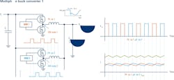
Each phase of a multiphase buck converter (interleaved converter) includes at least one set of switching transistors and one inductor. To leverage the benefits of multiphase operation, the on-times for the phases are carefully activated and shifted relative to each other.
This timing ensures that in high-load steady-state operation, all phases are active and equally shifted, with the supply current balanced across the phases. The phase-shifted operation minimizes ripple in both the supply current and the output voltage, which is essential for maintaining stable power delivery to high-speed SoCs.
At high current levels, conduction losses dominate. Multiphase buck converters offer superior efficiency and lower heat dissipation compared to single-phase converters — total current is distributed across multiple phases rather than being concentrated in a single stage.
Precise timing of the switching events is critical to maintain this efficiency and avoid excessive losses or thermal hotspots. In addition, balancing the operation across different phases helps evenly distribute thermal build-up across the components, which is essential for managing thermal stress caused by mechanical constraints and airflow.
Controller-based multiphase buck converters further enhance efficiency by dynamically adjusting the number of active phases based on load requirements. During high-load periods, additional phases are activated to distribute the energy demand, while during low-load periods, phases are deactivated to reduce switching losses.
Such dynamic phase management requires accurate timing coordination between the controller and the individual phases to ensure smooth transitions without introducing instability (Fig. 2).
Multiphase buck converters also exhibit excellent response to load transients. Since the on-times for the phases are staggered, the converter can quickly react to a load step by adjusting the pulse-width-modulation (PWM) signal for the phase that follows immediately after the load step. This rapid response minimizes voltage undershoots and overshoots, which are critical for maintaining power integrity in high-speed SoCs.
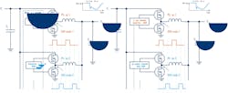
In stacked designs, the primary controller generates the PWM signal for all phases, providing a predefined phase shift between them (Fig. 3). Controller-based designs can dynamically align phases or activate/deactivate PWM signals for specific stages to further optimize timing and reduce transient-related errors.
While multiphase buck converters are powerful tools for improving performance and efficiency in high-speed SoC power designs, they also introduce challenges in validation and debugging. Timing must be carefully analyzed when validating phase management under static load conditions or dynamic load step scenarios to ensure proper operation across all phases.
Power Design Measurements on Multiphase Buck Converters
Effectively analyzing power designs that employ multiphase buck converters requires several critical measurements. Efficiency measurements are an essential starting point, as they evaluate how well the converter operates under varying loads and dynamic load scenarios.
These measurements assess the balance between power delivery and losses. Timing plays a significant role here, ensuring that the phases are properly aligned and the converter dynamically adjusts to changing conditions without introducing inefficiencies.
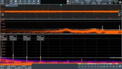
Another key aspect is the power integrity analysis of supply voltages for high-speed SoCs. This involves conducting measurements under both static-load conditions and dynamic-load step scenarios to ensure that the power rails meet strict requirements for noise, ripple, undershoot, and overshoot tolerance.
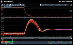
Since high-speed SoCs are highly sensitive to power fluctuations, these measurements are typically performed in both the time and frequency domains (Fig. 4). Timing is particularly important in this context, as the precision and synchronization of the phases directly influence the converter's ability to maintain stable voltage levels during fast transients.
Finally, phase analysis of the individual stages within the multiphase buck converter is crucial to verify proper operation. These measurements are performed under static loads as well as during defined load step scenarios to confirm that each phase reacts to load changes with minimal latency.
Accurate timing makes sure that the phases are not only properly shifted, but also dynamically managed to maintain low ripple and stable supply currents across all stages (Fig. 5). This includes validating that the controller effectively coordinates phase activation or deactivation in response to changing loads, enabling the converter to dynamically adapt while maintaining consistent performance.
How to Analyze Power Designs for High-Speed SoCs with Multiphase Buck Converters
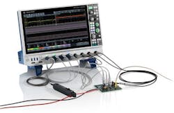
Modern oscilloscopes like the MXO 5 Series from Rohde & Schwarz are designed to address the challenges of power design and validation in high-speed SoC applications, particularly those using multiphase buck converters, where timing is a critical factor.
With eight analog channels and bandwidths of up to 2 GHz (in interleaved mode), the MXO 5 oscilloscope allows for simultaneous observation of multiple signals, such as supply voltages, PWM signals, and phase currents. This capability is essential for analyzing the timing and synchronization of phase-shifted signals in multiphase buck converters, ensuring balanced operation and minimal ripple in power delivery.
For mixed-signal designs, an optional 16 digital channels can be added without sacrificing any of the analog channels, enabling engineers to directly correlate timing relationships between analog power signals and digital control signals in complex power architectures.
The MXO 5 Series also offers the ability to synchronize with another MXO Series oscilloscope, enabling support for up to 16 channels. This standard feature combines waveforms from all instruments to the master MXO oscilloscope, enabling analysis with measurements, cursors, and even decoding to be performed across all channel waveforms.
The MXO 5’s hardware-accelerated acquisition rate of up to 4.5 million waveforms per second, paired with an FFT rate of up to 45,000 FFTs per second, offers high acquisition speed to capture and analyze rare or intermittent timing anomalies, transient disturbances, or glitches in power rails in real-time.
For example, when assessing load transient response in a multiphase buck converter, the oscilloscope can precisely capture how quickly the converter reacts to a sudden load step. It verifies if the timing of phase activations and deactivations is optimized to minimize undershoots, overshoots, and ripple.
The MXO 5 also provides an adjustable offset of up to 2 V (at 50 Ω) or up to 5 V (at 1 MΩ), even when set to its highest sensitivity of 0.5 mV/div. Combined with its 12-bit resolution (up to 18 bits in HD mode), the oscilloscope can detect small disturbances on DC power rails with maximum accuracy. Such precision is key for high-speed SoC designs, where supply voltage ripple or noise — if not properly timed and mitigated — can degrade system performance or cause operational instability.
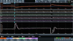
The instrument’s digital trigger system includes basic edge triggers, A/B/R sequence triggers, and advanced zone triggers. With the zone trigger, engineers can isolate specific timing-related events by triggering on user-defined zones from various signal sources, such as acquired waveforms, math waveforms, or spectrum views (Fig. 6).
This functionality is particularly useful when examining the timing relationships between the input and output signals of a multiphase buck converter, as well as when investigating phase-shift synchronization across multiple stages.
Furthermore, for automated testing workflows in power validation, the MXO 5 is available in a compact, 2 HU form factor without a display (MXO 5C), enabling remote control in automated test setups. This configuration facilitates efficient and repeatable timing analysis across different load conditions, power-rail configurations, and SoC designs.
Probes and Accessories for Power Design Measurements
To measure perturbations on power rails, the R&S RT-ZPR power-rail probe is well-suited as a companion to the MXO 5 Series. This 1:1 probe offers the sensitivity required to detect small disturbances while maintaining the accuracy needed to measure DC power rail voltages.
The probe features a built-in DC meter, which automatically subtracts the DC offset in the oscilloscope’s offset circuitry. This functionality allows engineers to use the oscilloscope’s full sensitivity to accurately measure disturbances such as ripple, noise, and transients, while still displaying the actual DC voltage of the power rail. This is important in high-speed SoC designs, where timing precision is critical in mitigating noise and ripple during high-current operation.
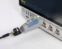
For power designs with high supply currents, ground-loop effects can introduce measurement errors. These effects are particularly problematic in multiphase buck converters due to the high current levels in the various stages. To address this, the R&S RT-ZPR probe, when combined with the Picotest J2115A coaxial isolator, can help reduce ground-loop errors, leading to accurate and reliable measurements of power-rail behavior (Fig. 7).
When analyzing the switch-node voltage in multiphase buck converters, differential probes such as the R&S RT-ZD can be highly effective. These probes eliminate ground-loop effects when measuring the timing of switching events — a key factor when validating the efficiency and synchronization of the converter’s phases. Accurate timing measurements of switch-node voltages are essential in terms of the converter operating optimally under varying load conditions.
In addition, the R&S RT-ZC Series current probes and Rogowski coils are tools used to measure current and calculate instantaneous power for efficiency analysis. These probes allow engineers to observe current waveforms across multiple phases and correlate them with timing-critical PWM signals, ensuring a comprehensive understanding of power delivery and efficiency in the system.
Summary
Test solutions like the MXO 5 and MXO 5C series oscilloscopes are well-suited for analyzing power integrity in high-speed SoC power designs, enabling precise timing analysis of noise, ripple, undershoots, and overshoots with high sensitivity. The ability to synchronize multiple instruments further extends channel availability, and the acquisition speed and triggering system facilitate efficient detection and analysis of power-rail disturbances in both the time and frequency domains.
And when paired with dedicated probes like the R&S RT-ZPR power-rail probe, differential probes, and current probes, the oscilloscopes provide a complete solution for validating PWM signals, phase synchronization, and load transient response across all stages of a multiphase buck converter.
Read more articles from this special report
About the Author
Martin Stumpf
Segment Manager, High-Speed Digital Test, Rohde & Schwarz
Martin Stumpf is Segment Manager, High-Speed Digital Test, at Rohde & Schwarz.
