Special Report: RF/Microwave Test
This article appeared in Evaluation Engineering and has been published here with permission.
Download this article in PDF format.
What you'll learn:
- Advances in hardware, including OTA test chambers, VNAs, and spectrum analyzers.
- Advances in software involving modeling and simulation platforms.
- Insider perspectives on challenges facing the test industry.
Increasing complexity and the need for higher frequencies and bandwidths, multiple channels, low-power operation, and space constraints are placing considerable demands on RF/microwave test equipment. Solutions extend from simulation software to bench, modular, and portable instruments to complete systems, for applications from R&D to compliance test and field service.
“The RF/Microwave test field is witnessing a profound change related to the diffusion of technologies using RF signals (and, in the most advanced applications millimeter-wave signals) to communicate, transfer, and exchange information,” according to an email message from Keysight Technologies. In the last few months, the company has introduced several hardware and software solutions.
“On the software side, Keysight’s PathWave integrated software suite plays a critical role in 5G and mmWave design, verification, and test methodologies,” the company said. “PathWave software streamlines the entire workflow from system-level modeling to RF/microwave circuit co-simulation and analysis. Companies like Nokia Bell Labs rely on PathWave and the entire Keysight ecosystem to gain the valuable engineering insights they need to push wireless technology to the next level. Keysight is also collaborating with Nokia on a new software approach that leverages artificial intelligence and advanced data analytics in the company’s 5G base station manufacturing processes, significantly improving test efficiency.”
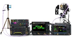
On the hardware side, Keysight in 2019 introduced what it calls the first single-box multichannel solution for wideband mmWave measurements. “Based on the UXR-Series of oscilloscopes, it delivers fast, affordable, coherent analysis for wideband measurements up to 110 GHz. This solution accelerates the development of next-generation mmWave communications, satellite communications, and radar applications,” Keysight said.
Characterization to Production
Rohde & Schwarz is addressing various aspects of RF/microwave test, including characterization, network rollout, automotive radar, and cross-channel measurements, according to Markus Lörner, market segment manager industry components, research and universities.
For network rollout, Lörner said, 5G operators can employ the R&S TSME30DC drive-test scanner. “Networks anchored in LTE, or making use of dynamic shared spectrum (DSS) to transmit 5G-related data using part of the LTE spectrum, or with separate networks utilizing FR1 and FR2 frequencies, can scan both frequency ranges simultaneously to save time and effort, by using the R&S TSME30DC with a suitable drive-test scanner,” he said, adding that frequencies from 450 MHz to 6 GHz and 24 to 30 GHz can be scanned simultaneously.
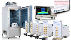
Lörner pointed out that automotive-radar applications are migrating from the 24-GHz band to 79-GHz. “The 4-GHz instantaneous bandwidth greatly improves the range resolution, accuracy, and reliability of object detection, and the higher frequency reduces the device size. The R&S ATS1500C over-the-air antenna test chamber has been designed to meet requirements for 79-GHz automotive radar test, for R&D, validation, and calibration, in combination with the R&S AREG.”
The R&S ATS1500C features a CATR reflector, providing a 30-cm diameter quiet zone—large enough to test the largest automotive radar sensor aperture used for the frequency band, Lörner said, while the R&S AREG100A automotive radar echo generator can include interference while generating up to four echoes simultaneously, all with the in-demand 4-GHz maximum instantaneous bandwidth.
According to Adam Smith, director of product marketing at LitePoint, the company’s product focus for 2020 is in three main areas: 5G, both sub-6-GHz FR1 and mmWave FR2; Wi-Fi 6E, utilizing the 6-GHz unlicensed band; and Ultra-Wideband (UWB), based on an emerging application space in accurate positioning and ranging.
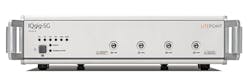
“LitePoint has recently released new products to address the unique technical requirements of each of the technologies listed above,” Smith said. First, he described the IQgig-5G Model B as “Our second-generation 5G mmWave product focused on scaling 5G mmWave FR2 end-products to high-volume manufacturing. Currently, the IQgig-5G is the only fully-integrated mmWave test system in the market, deployed on manufacturing lines testing up to four devices in parallel. Further, IQgig-5G offers best-in-class error vector magnitude (EVM) performance across all existing and forthcoming 3GPP bands, in a contiguous 23- to 45-GHz range.”
Smith said the IQxel-MW 7G is specifically targeted at testing Wi-Fi 6E products. “The IQxel-MW 7G is a fully-integrated wireless connectivity test solution that addresses the high-performance needs of products launching later this year, operating in the new 6-GHz unlicensed band (6 to 7.125 GHz),” he said. “IQxel-MW 7G is a reference solution at silicon solution providers, backward-compatible with LitePoint’s widely-deployed installed base of IQxel family testers, enabling companies integrating the latest Wi-Fi technology to get to market (and volume) quickly.”
Smith also commented on the IQgig-UWB. “UWB technology introduces some very unique requirements that do not conform to traditional wireless connectivity standards like Wi-Fi or Bluetooth,” he said. “Specifically, UWB operates in a frequency range up to 10.6 GHz at instantaneous signal bandwidths of approximately 500 MHz to more than 1 GHz. Additionally, instead of metrics like EVM that we have been accustomed to testing in OFDM-based technologies, UWB’s performance metric is focused on accurate measurement of timing. IQgig-UWB uniquely includes a precise trigger mechanism to enable accurate time-of-flight (ToF) and jitter measurements for UWB products.”
VNAs and Device Models
Wayne Wong, product marketing manager at Anritsu, cited a key challenge for RF/microwave test. “Accurate circuit simulation is important for rapid deployment of emerging RF/microwave communication systems because it provides accurate predictions of new designs,” he said. “The result is greater chance for first-time design turns. First-time release becomes even more critical when the design cycle includes on-wafer development.”
Wong continued, “The key aspect for accurate circuit simulation is precise device models, which are developed using a VNA with as wide of bandwidth as possible. The universal migration of microwave components towards on-wafer media is driven by the need for compact subsystems, economies of scale, and highly-integrated systems for improved performance. The VectorStar ME7838G 220-GHz broadband system performs ultrawide single-sweep frequency characterization for optimal device characterization and accurate circuit simulation.”
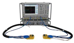
Wong said the VectorStar ME7838G system primarily supports on-wafer measurements where device characterization is required. “R&D device characterization for circuit simulation during the design phase of communication circuits is the first line of targeted applications, and can also be used in production environments where multiple circuits within wafers need to be verified.“
He continued, ”the ability to test a wide range of circuits from 5G cellular to D-band radios, means that when the ME7838G system is installed a probe station can be quickly and efficiently transformed for different application measurements. This can be done without having to dismantle the VNA and reconfigure for mmWave waveguide measurements.”
Another key test challenge is to continually address higher frequency requirements in a cost- and space-efficient way, Wong said. “Removing the effects of cable and fixturing to achieve more accurate test results becomes more difficult, as frequencies climb and calibration standards become harder to implement on-wafer or in the form factor of the test fixture.”
Angus Robinson, Anritsu’s product marketing manager, added, “For field testing, we see increased levels of spectrum interference and the need to identify nefarious signals. There is also more passive intermodulation (PIM) distortion in cellular networks. All of this means over-the-air (OTA) measurements of 5G mmWave radios are becoming more important.”
In addition to the VectorStar ME7838G VNA, Anritsu offers the MS46131A 1-port VNA, the newest instrument in the ShockLine family. “It is available in three frequency ranges, including to a market-leading 1-port sweep range of 43.5 GHz,” Wong said. “It is also modular, with the software on a single PC configuring one or two MS46131A VNAs on a session-by-session basis for excellent test setup flexibility.”
The ShockLine MS46131A VNA targets production test of a range of RF and microwave components, Wong said, adding, “The performance supports limited design and verification requirements and the small form factor supports portability between test sites.”
Wong also cited Anritsu’s ONA (Optoelectronic Vector Network Analyzer), describing it as suitable for opto-electronic device characterization at frequency ranges up to 40/70 GHz for 850-nm/1,310-nm/1,550-nm wavelength devices. “The modular system is built on Anritsu’s VectorStar VNA, and users can easily conduct electrical, electro-optical, or optical measurements. “The modular architecture of the ONA systems allows it to be used in all phases of a product life-cycle—from R&D to test verification and through production.”
Robinson commented on portability. “The Field Master Pro MS2090A battery-powered handheld spectrum analyzer has been enhanced with IQ capture and streaming with 110-MHz bandwidth, enabling new applications for government agencies needing to monitor secure spectrum. It interfaces directly to the industry-standard Bird IQC5000B record and playback system.” He added that the Field Master Pro MS2090A is used for R&D and spectrum monitoring and protection applications.
According to Brandon Malatest, COO at Per Vices, “Our Cyan platform is our latest release and pushes the limits of RF/microwave test equipment. The flexibility offers an extended operating frequency from near DC to 18 GHz, a customizable number of radio chains (up to 16), both transmit and receive functionality, with high bandwidths available (1 GHz per radio chain with possibility to extend to 3 GHz), and able to be optimized for high dynamic range or aggressive channel-masking applications as required.”
Malatest said the company’s products have been used in each stage of a product lifecycle. “Where the initial stages of R&D are typically serviced by our stock products, we do work with our customers to ensure we optimize the platforms to meet their specific production or field-test requirements.” This optimization can include the incorporation of additional IP; development of custom radio stages to accommodate noise, filtering, or channel-masking requirements; and mechanical and environmental changes, he said.
RF/Microwave Switching
Pickering Interfaces addresses switching. “We have focused on two areas in our product portfolio—first, our 40-88X solid-state switch family has been updated from a 6-GHz bandwidth to 8 GHz,” said Bob Stasonis, technical product specialist. “In addition, our microwave switching family now has bandwidth expanded to 67 GHz. With the expansion of 5G developments and rollouts, this is an important change. Our present PXI offerings feature 420 RF and microwave module choices. In addition, there are presently over 70 RF and Microwave LXI switching systems in our catalog.”
Stasonis commented on applications. “Our RF and microwave offerings have been used primarily in MIL/aero applications, most of which we are not allowed to discuss, but we assume that a lot of our products are used for testing communications and radar systems,” he said. “In automotive, our impedance-controlled fault-insertion modules are part of HILS systems testing automotive networks. The addition of the 67-GHz switching products makes Pickering a provider for testing 5G devices. We have also recently been working in the healthcare industry to replace older, obsolete GPIB microwave switching.”
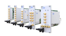
VTI Instruments, a product line in AMETEK’s Programmable Power business unit, also addresses switching. The company recently introduced its SMX-7xxx Series of 15 PXIe microwave switch modules, according to Chris Gibson, senior product manager. “These new modules extend functionality typically reserved for dedicated standalone systems into the PXIe form factor. The 26.5-GHz bandwidth operation as well as single- and dual-slot versions provide the ability to create multiple configurations, including SPDT, SP4T, SP6T, and transfer switches.”
He continued, “a pass-through adapter module extends functionality even further with programmable drive lines for controlling attenuators and other microwave devices. Embedded web-browser control further simplifies setup and test debugging, which allows all relays to be controlled independently of application software and device drivers.”
Amplifiers, Analyzers, and Generators
AR RF/Microwave Instrumentation continually releases updated amplifier models, according to Dale Hauck, applications engineer. “Of particular interest is AR’s line of S-series amplifiers, spanning from 0.7 to 18 GHz,” he said. “These amps, along with all of AR’s amps, offer the widest bandwidth, highest output power, longest life, and best mismatch tolerance on the market.”
Hauck added that AR’s amplifiers serve in all stages of product life cycle, including R&D, production test, and field test. “AR amps are actively used for each of the stages, whether it’s characterization testing, production chip testing, product compliance testing, or radar communications in the field, as well as many other applications,” he said, adding that the company serves 5G, Wi-Fi 6, automotive radar, IoT, radar, and EMC compliance. He further noted that AR has formed strategic partnerships with companies including Keysight, Comtest, and Nexio to provide total solutions for customers.
Tabor Electronics has recently introduced two RF/microwave test products, according to Mark Elo, US manager. The first is Proteus, “...a 9-GHz bandwidth arbitrary waveform transceiver that not only generates directly to RF and microwave frequencies, but also has a receiver architecture with FPGA processing built in. This allows you to generate real-time signals based on feedback from the receiver, which are then processed onboard in the FPGA.”
The second is Lucid, which, Elo said, redefines analog signal generation. “This 12-GHz modular instrument has specifications comparable to leading bench/rack instrumentation,” he said, adding that it is available in four form factors: a basic brick module, a multichannel unit for R&D and production (available in benchtop or rack-mount models), and a portable version for field support.
Elo commented on applications. “Proteus focuses on wide-bandwidth applications in the communications, automotive, electronic warfare, and physics verticals, and can generate up to 4.5 GHz of instantaneous bandwidth. This is frequently used in signal-simulation applications for emulating next-generation wireless systems, such as Wi-Fi 6 and 5G, and radar signals for automotive and electronic warfare applications. We also simplify the quantum-physics experiment setup by providing the ability to generate signals direct to microwave, eliminating the need for complex measurement setups.”
He added that Lucid has broader applications. “It has been used in EMI applications, chamber test (especially with the increase in frequency ranges driven by Wi-Fi 6 and even UWB systems), product RF calibration systems, military field test, multichannel applications such as those required in up-and-down conversion chains, and other applications where multiple channels of coherent carriers are required.”
Several companies have recently introduced signal and spectrum analyzers. For example, B&K Precision's 2680 Series spectrum analyzers, offer frequency ranges from 9 kHz to 2.1 GHz, or to 3.2 GHz. “Each model includes advanced measurements such as channel power, adjacent channel power, occupied bandwidth, total power, and third-order-intercept, along with a 2D and 3D spectrum monitor,” said Jamie Pederson, product marketing manager. “The standard preamplifier, tracking generator, and 1-Hz minimum RBW round out the list of features,” he added.
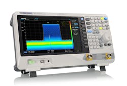
Siglent’s RF development team has been busy this year, according to Jason Chonko, applications marketing manager, Siglent North America. “We announced 7.5-GHz additions to our swept-superheterodyne and VNA product lines, as well as our first real-time spectrum analyzer series, the SSA3000X-R. They all feature solid RF performance, easy-to-use UI, and toolkits that really tailor the instruments for EMI, broadcast, and RF development work.”
In addition, Keysight launched the N9021B MXA X-Series Signal Analyzer to meet the evolving needs of advanced wireless communications design-validation-and-test and manufacturing engineers. According to Lörner at Rohde & Schwarz, the R&S SMBV100B vector signal generator and the R&S FSVA3000 spectrum analyzer provide heavy-lifting RF test solutions for the production line. A subsequent article will provide details on signal- and spectrum-analysis tools.
USB Vector Network Analyzers
Copper Mountain Technologies focuses on USB vector network analyzers. “We introduced lower-cost M models of our Compact Series vector network analyzers, which provide the same great metrological performance at a very competitive price, as an economical option for engineers who don’t need advanced features in the software,” said Brian Walker, senior RF design engineer. “We also introduced SC models for our Compact Series vector network analyzer series with 16-ms measurement speed, more dynamic range, and higher output power.”
Walker said the company’s VNAs are used throughout the lifecycle of many RF products. “VNAs are used in the design, manufacturing, and ongoing preventative maintenance in the field for RF and microwave products, and is a critical measurement tool for all RF applications. Our customers participate in a wide variety of applications, such as 5G, IoT, automotive, defense, and more. Our VNAs are easy to integrate into a test system, helping them to work seamlessly in many types of industries and applications.”
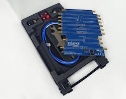
Pico Technology also offers USB VNAs and has been emphasizing education. “The explosive growth of RF, microwave and ether-borne applications, particularly in the 1 to 6 GHz spectrum, is drawing more engineers, students, technicians, scientists, educators, and even medical professionals, into a field that they have not previously had to master,” said Mark Ashcroft, RF business development manager. “Training in RF, microwave, and propagation disciplines, whether in design, test and measurement, or field support of RF systems, has needed to spread rapidly to an ever-wider audience.”
He explained, “skills in network, antenna matching, testing, and metrology are of course central to that. Fortunately, the low-cost USB vector network analyzer has brought affordable professional-grade measurements to educators and students alike. This enables unprecedented access to instrumentation and calibration standards to practice techniques and gather real-world measurements in the classroom or on every desk.”
Ashcroft continued, “Adding value and flexibility to the highly successful PicoVNA 106 6-GHz Vector Network Analyzer, Pico Technology has recently announced its Network Metrology Training Kit and two important interfaces to major CAD software products. Partnered with the PicoVNA, or indeed any other VNA, Pico’s Network Metrology Training Kit provides, in a single carry or storage case, a variety of passive and active test networks and low-cost calibration standards and test leads. A teacher and student need only these to begin the practice of calibration, measurement, and feedline elimination techniques and to explore and compare errors that can arise. The kit is provided with a comprehensive user/training guide, useful instrument settings files, and typical calibration standard and de-embed data.”
Ashcroft said a trainer can optionally add professional-grade calibration standards, test leads, and verification standards. “Expanding the initiative to cooperation with others, Pico has also become a Cadence AWR Connected Partner by integrating the PicoVNA directly to the AWR Design Environment. A freely downloadable software wizard provides remote control of the PicoVNA and single-touch data transfer from live on-screen measurement directly into your Microwave Office project—perhaps into a comparative plot or as measured data for use in simulation.”
From Chassis to Thermal Platforms
Pixus Technologies, a provider of embedded computing and enclosure solutions, offers products such as a 6U OpenVPX chassis platform with a mix of VITA 66.4 optical connectors and VITA 67.3 RF connectors. “The VITA 67 standard brings RF capability to OpenVPX open-standard architecture systems,” said Justin Moll, vice president of sales and marketing. “The products can serve in both prototype test and deployed systems, addressing applications including radar and C5ISR.”
“We are working with board vendors for backplane/chassis solutions that are interoperable with their OpenVPX/RF modules,” said Moll. “We've also worked with government labs and institutions to provide VITA 67 and OpenVPX chassis platforms for their development. Our open-frame test enclosure provides easy prototyping for SOSA/HOST and other OpenVPX applications utilizing RF. With a wide range of VITA 67/OpenVPX backplanes, Pixus can leverage existing designs for a customized solution for most applications.”
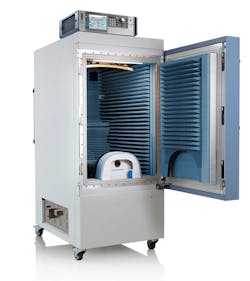
TotalTemp addresses thermal RF test, and the company has recently introduced larger sizes of thermal test platforms. For example, their Model SD288 addresses fast and efficient testing of larger or multiple RF modules, according to John Booher, chief technology officer.
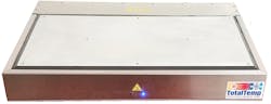
The platforms serve in both R&D and production test, supporting customers’ challenges in obtaining effective heat transfer for their RF modules. He cited an easy-to-use temperature controller with advanced automation and temperature control as a key feature of the platform.
Ground-Vehicle Radar
dSPACE addresses the ground vehicle market. “For over 30 years, dSPACE has been delivering tools to the ground vehicle engineering community for developing and validating in-vehicle software,” said Vivek Moudgal, their vice president, of business development, dSPACE Inc., and Andreas Himmler, senior product manager, autonomous driving systems, dSPACE GmbH. “For the community working in the ADAS and AD domains, dSPACE has developed both hardware- and software-based tools to allow the community to speed up their design and verification work and deliver robust and reliable functionality to the consumers.”
They added that the company has been integrating best-in-class products into its offerings for automotive radar applications. “In early 2019, dSPACE partnered with ITS and miro·sys and acquired IP, which will continue to be refined to provide the engineering community with the tools they have come to expect from dSPACE.” DARTS (dSPACE Automotive Radar Test System) is the company’s offering to the automotive radar development and testing community.
“In early 2019, dSPACE released a series of compact DARTS systems (DARTS 9030-M, DARTS 9020-S and DARTS 9030-MS) with very high capability and performance,” Moudgal and Himmler said. “These devices are designed to serve multiple segments of the value chain, from radar chip designers to ECU developers, as well as OEMs for function validation. More recently (at the end of 2019), dSPACE released a new offering—the DARTS 9018-D, designed for end-of-line use by Tier 1 suppliers, OEMs, and the aftermarket.”
They explained, "Depending on the model, the available bandwidth is 1.2 GHz or 4 GHz, and with a simple change of the radio front-end (one connection for each RX and TX), the base unit can be switched to work supporting K-band radars to E-band radars or vice-versa. The K-band range supports 23 to 26 GHz, and the E-band range supports 75 to 82 GHz as a standard.”
They continued, “Based on application needs, DARTS devices are capable of simulating targets at distances of less than 1 m, all the way to 1,000 m, with 6- or 10-cm resolution over the entire distance simulation range. With the capability to simulate Doppler frequencies of ±700 km/h, these devices are capable of being used for all known ground-vehicle applications where relative speed measurement is needed.”
They added that DARTS devices can be used in R&D, production testing, and field testing as well as in aftermarket—body shops, Periodic Technical Inspection (PTI), etc.—applications. “Their compact size and ability to be powered by DC power sources makes them extremely portable and easy to package,” they said. “Another specialized use case for DARTS is for closed-loop function validation using a hardware-in-the-loop setup.” They concluded.
Device Perspective
Randy Oltman, RF and high-speed instrumentation segment director at Analog Devices, cited two main challenges to the RF test and measurement industry, both related to 5G. “First, millimeter-wave 5G continues to push towards 50 GHz with successful auctions in the 39-GHz and 47-GHz bands,” he said. “3GPP defines frequencies above 50 GHz, but band allocations and licensing worldwide for 50 to 55 GHz is less clear. However, test and measurement makers designing new equipment want to be considerate of future needs and look to push frequency coverage as high as possible.”
Oltman continued, “Second, OTA methods are not finalized for testing mmWave 5G devices with embedded antennas. Finding an appropriate method that allows rapid testing of mmWave devices in production will be essential to the a mass rollout of mmWave devices. ”
Oltman said Analog Devices’ advanced RF modeling and packaging expertise enables development of novel and higher performance parts. “RF-considerate multi-die packaging dramatically reduces parasitics leading to superior broadband performance, highly important for instrumentation,” he said. “Further, these multi-die devices integrate common functions which are usually discrete, greatly reducing PCB area and simplifying the design through fewer parts.”
Oltman cited several recently introduced devices, including the ADPA7006. “This new part joins the recently launched ADPA7002 and ADPA7005,” he said. “These 18- to 44-GHz mmWave amplifiers, with power levels up to 1 W, are available both in SMT and die form. These devices offer a unique novel combination of power and bandwidth, with up to +42-dBm OIP3 and 31-dBm P1dB.”
Other recently introduced parts include the ADF4372 16-GHz single-chip synthesizer, ADMV8420/ADMV8416/ADMV8432 tunable band pass filters, ADRF5043 SOI switch, LT3072 dual LDO, and LTM8078 Silent Switcher. With regard to the LTM8078, he said, “These are one of the lowest-noise switching regulators in the industry. Previously, a designer never would consider powering a VCO or amplifier with a switching regulator. The LTM8078 is the latest in the line of silent switchers that are game changers for applications where greatly improved power efficiency and/or large regulated voltage drops are required.”
Simulation and Modeling
Ansys offers modeling and simulation solutions to design RF/microwave and wireless communications devices for a broad range of industries, according to Manohar Raju, their senior product specialist at Ansys. “These solutions are used to compress the number of tests and design cycles,” he added.
The company recently introduced key solutions in RF/microwave and wireless communications. “We are the first to offer a novel solution to model antenna arrays used in diverse applications,” Raju said. “Significant increase in speed and accuracy as well as decreased memory requirements are the key benefits of this solution in Ansys HFSS.”

He continued, “A new product in our portfolio, the Ansys RaptorH employs HFSS to extract S-parameters and parasitics for RFICs with unprecedented speedquickly and accuracytely.” He explained that S-parameter data is fed to circuit simulators to predict the signal integrity of these components. “Similarly, SI issues for large and dense PCBs and packages are analyzed by hybrid solutions of HFSS and SIwave to take advantage of their best attributes and yield S-parameter data of superior accuracy,.” he added.
Further, Raju said, “Designers of RF components and systems must ensure that their devices do not cause unintended emissions, radiations, or overstep regulatory standards. In-built EMI/EMC 3D components of Ansys HFSS and uniform simulation workflows help achieve compliance faster and economically for electromagnetic impulse (EMP), conducted emissions CISPR25 and CISPR2, and other standards.”
Remcom offers tools including XFdtd electromagnetic simulation software, WaveFarer automotive radar simulation software, and Wireless InSite 3D wireless prediction software, according to Stefanie Lucas, director of marketing. The products support R&D and simulated testing, across a variety of verticals, including 5G, Wi-Fi, automotive radar, IoT, indoor consumer electronics (smart speakers, laptops), mobile device design, and wireless network planning, she said.
XFdtd includes full-wave, static, bio-thermal, optimization, and circuit solvers, and can simulate electrostatic discharge (ESD) testing, enabling engineers to identify potential locations of dielectric breakdown and components at risk of damage. The automotive version of WaveFarer supports drive scenario modeling at frequencies beyond 79 GHz. A, and Wireless InSite supports the analysis and design of wireless systems for communication, networking, sensors, and other applications in urban, indoor, or rural environments.
MathWorks offers a range of tools for wireless and radar system design. “These tools are built on our platform products, MATLAB and Simulink,” said Rick Gentile, product manager, RF and signal-processing systems. “The tools cover RF, antenna, and phased-array design and analysis. They also cover the signal-processing and data-processing system components.”
Gentile said modeling building blocks, algorithms, and system simulators are available for standards-based wireless systems including 5G NR systems. “We also support broad workflows for multifunction radar design,” he added. “System developers use our tools to ensure architectures and designs will work at the earliest point in the project life cycle. The unique aspect is that MATLAB and Simulink as platforms span such a broad range of disciplines and a broad range of workflows (requirements analysis through deployment on hardware). This enables a development environment that eases system-level integration across diverse teams at the very earliest stages of a project.” Building on that foundation, MathWorks’ most recent solutions are available in the company’s R2020a release, which became available for download in March.
Gentile cited a challenge that faces test vendors and customers across the RF/microwave arena. “We see the rise in system complexity as the main challenge,” he said. “This complexity is driven by many external factors such as the need for higher bandwidth, lower power systems. The RF spectrum is crowded and the chance for interference is greater than ever. Systems that previously were focused on a few key functions now need to perform a more diverse set of tasks. Today’s systems also get deployed in ways that were never possible in the past.”
Gentile noted further that system development teams may be smaller today than in the past and are likely to be spread out across the world. “All of the challenges described above add risk,” he said. “Our goal is to make it easy for system developers and integrators to model and simulate their systems before they build them. Finding issues early in a project greatly reduces the cost in fixing these issues. We want to help reduce risk. We also want to help system developers leverage all of their modeling work by making it easy to deploy code directly from models. System reliability is critical, so we work to make it easy to verify designs directly from the modeling results as well.”
Markets and Challenges
EE asked contributors to this report to elaborate key features of their offerings and to comment on the markets they serve and challenges facing the industry. Read on to see what they had to say.
What are Other Key Features of Your Solutions You Would Like to Emphasize?
Moudgal and Himmler, dSPACE: “Characteristics that describe DARTS devices include ultra-compact, lightweight, low-power-consuming, RUT-modulation-scheme-agnostic, and quick-changeover between K-band and E-band applications. Industry-leading performance makes DARTS a very versatile instrument for a wide range of applications, from radar chip design and calibration to end-of-line testing at Tier 1s and OEMs, to function validation in the lab, and to aftermarket applications.”
Stasonis, Pickering Interfaces: “Our customers really appreciate the LED switch-path status indicators on our PXI and LXI products. It allows them to visually see if their code is closing the correct switch. Our customers who are configuring a large number of microwave switches and multiplexers into a complex configuration have found that our Switch Path Manager (SPM) signal-routing software makes programming their switching system extremely easy. Once the test engineer has defined the cabling interconnections, all that is necessary is to program a particular test point that is to be connected to a particular instrument, and SPM automatically makes the necessary connections.”
Gibson, VTI Instruments: “VTI custom RF interface units (RFIUs) are switch systems designed to meet customer specifications that require integrating the RF source and measurement instrumentation with the device(s) under test. RFIUs allow signals to be routed, attenuated, combined, split, filtered, and amplified. AMETEK provides RFIU customers with a combination of the following services: RF engineering for component selection and system design; control engineering for signal routing management; mechanical engineering for enclosure design, component layout, and temperature control; software engineering for development of both an LXI-based virtual front panel and IVI drivers, and complete documentation and test data for accurate reproduction of the system as needed.”
Wong, Anritsu: “The ShockLine and VectorStar families of VNAs take advantage of Anritsu’s patented Non-Linear Transmission Line (NLTL) technology to achieve higher frequency capabilities in more compact and cost-efficient packages. Many ShockLine models and VectorStar modules are compact enough to direct connect to the DUT or on-wafer probe, thus minimizing cable and fixture losses and maximizing measurement stability.
"ShockLine VNAs also offer Anritsu technology developed for the high-end VectorStar VNA family to de-embed fixtures and probes using partial calibration standards with the Universal Fixture Remove (UFX) option. The NLTL harmonic samplers provide the highest third-order intercept (TOI) performance that enables high-performance measurements of active devices in the VectorStar VNA line.
"The Anritsu ONA solution takes advantage of the NIST traceability (with an in-house calibration lab that characterizes all the customers' OE modules) for the OE modules for traceable measurements. The flexibility and upgradability in terms of frequency for the VNA, the OE module, and the EO convertor is a considerable advantage to our customers.”
Raju, Ansys: “Ansys is the first to offer a novel solution to accurately model antenna arrays for applications such as 5G mmWave base stations and microcells, automobile radars, satellite communications, aerospace, naval, etc. Leveraging HFSS 3D Component, the technique is built upon the HFSS Domain Decomposition method (DDM) for large-scale analysis, and is a breakthrough technology for solving large and complex arrays. It eases the burden of matrix factorization and decreases memory requirements resulting in significantly faster array simulations.”
Malatest, Per Vices: “Our products aim to meet the needs of many customers out of the box; however, some customers do have strict requirements that are not met by the stock products. For these customers, we work very closely to leverage the flexibility of our platforms along with our existing IP to help develop a solution to meet their needs. For our existing customers, this has resulted in a more cost-effective solution, faster time to market, and higher performance platform than any alternative.”
Smith, LitePoint: “Usually, when we look at the increasing technical requirements of new wireless technologies, it is usually tied to something related to a more advanced modulation technique and a race to higher data rates. However, with the emergence of UWB technology, we find a completely different set of requirements. Instead of jamming gigabits-per-second through the air, UWB technology (specifically the 802.15.4z IEEE standard amendment) uses very short pulses to transmit information that enables a companion device to accurately determine its relative distance and direction.
“The ‘money spec’ in UWB is time, or more specifically, time-of-flight (ToF). ToF is not only useful for accurately determining location, it is more importantly able to provide an additional layer of security to an application by enabling improved location authentication. Other wireless technologies (such as Bluetooth) can be intercepted and rebroadcasted to ‘fake’ the appearance of location (aka, a relay hack). This allows a thief to steal your wireless car key, or even credit-card information, if they can get physical proximity to your transmitted signal. The time-based nature of UWB does not allow for this kind of vulnerability. It is relatively simple to defeat signal-strength (RSSI) authentication methods. It is very difficult to defeat methods that rely on the authentication of a time stamp.
“Accurately calibrating and measuring the performance of UWB devices requires the test equipment being able to very precisely measure and respond to a device in time. For example, in 1 ns a radio signal travels approximately 30 cm. In order to know a location with roughly 10-cm accuracy, the timing precision of the measurement equipment needs to be less than 100 ps. LitePoint’s IQgig-UWB test system has a timing architecture that enables this level of timing and response repeatability.”
Keysight: “Modern devices are highly integrated. As a result, wireless and high-speed-digital engineers often test devices with more than four ports. In wireless RF, front-end modules (FEM) for multiband operation and MIMO antennas require multiport characterization for all their components. Testing high-speed digital technologies like HDMI and USB 3.1 is even more tedious. Not only do digital cables have multiple internal cables and connectors, but each must undergo testing twice— once in the time domain, and once in the frequency domain. The need for multiport test accelerated the development of switch-based solutions for traditional vector network analyzers (VNAs). When switch-based solutions were not adequate to keep up with multiport test, the VNA itself was re-imagined and optimized for multiport test.”
What Vertical Applications Areas Do Your Products Serve?
(Editor’s note: Many contributors to this report provided details on 5G and Wi-Fi 6 test, which will be the subject of a subsequent article.)
Wong, Anritsu: “The VectorStar ME7838G and ONA solutions address the needs of designers developing solutions for 5G, automotive radar, microwave backhaul communication links, opto-electronic markets, and other applications with high-speed data throughput. The MS46131A ShockLine VNA targets 28-GHz and 39-GHz 5G antenna testing, along with other microwave 1-port applications.”
Robinson, Anritsu: “Field applications, including interference hunting, spectrum protection, and 5G NR installation and maintenance, are where the Field Master Pro MS2090A is used.”
Malatest, Per Vices: “Our products are being primarily used for applications in the following markets: radar systems, medical-imaging systems, radio links and mobile base stations, and GPS navigational systems. The specific functionality depends on the markets and the customers; however, the use of our products as test and measurement equipment has been present in each of the above.”
Gibson, VTI Instruments: “VTI RF/microwave switch systems serve all the wireless telecommunication and wireless industrial applications. VTI switch systems are not limited to testing a specific wireless protocol.”
Raju, Ansys: “For automotive, our tools accurately simulate RFICs and the standalone and installed performance of radar. Engineers virtually recreate dynamic ADAS scenarios involving V2V and V2X communications in Ansys HFSS SBR+. Finally, with Accelerated Doppler Processing capabilities following simulations in Ansys HFSS SBR+, vehicle radar sensors are accurately evaluated. ADP uses high-fidelity simulations to model synthetic radar signatures from automotive radar sensors with unmatched speed and efficiency. It’s difficult and costly to test and measure active safety scenario corner cases, such as an autonomous-car driving scene involving a pedestrian crossing the road. Using Ansys simulation tools is economical and faster to study regular, corner, and edge cases. Moreover, simulation also be used to consider cases involving potential loss of life and property damage.”
Gentile, MathWorks: “Our customers work across a broad spectrum of applications across all industries. Wireless technology is ubiquitous and enables connectivity across the board. This standards-based wireless connectivity including 5G, Bluetooth, and WLAN. We also enable radar system development for commercial (for example, consumer, automotive radar) and aerospace/defense applications.”
Moudgal and Himmler, dSPACE: “The current line-up of DARTS is specifically designed to support the K-band (24 GHz) and E-band (77 GHz) automotive radar programs. In the future, if other frequency bands are needed, the DARTS devices are easily upgradable by switching out the radio front-ends to match the frequency band of interest.”
What Do You See as Key RF/Microwave Test Challenges?
Chonko, Siglent: “I think that a key area of development is knowledge, and the gap between new engineers and folks that have been in the industry for a long time. Over the past 10 years, the interest in RF has ballooned, but I’m not sure that the number of engineers with practical experience has matched the need. Many experienced engineers are retiring, and this may leave a significant gap in what we can do today vs. where we go tomorrow.”
Raju, Ansys: “Designing RF/microwave devices and communications systems to be successful requires ensuring precise signal integrity, accuracy, and fidelity of RF devices, systems, packages, and antennas. With miniaturization, more ICs, SoCs, packages, and wireless systems are being integrated into a single high-speed digital device. This could create interference due to unwanted out-of-band emissions by co-located RF systems (RF cosite) as well as broadband noise and harmonics by digital signals (RF desense).
Stasonis, Pickering Interfaces: “From a switching standpoint, as frequency increases, the interaction with the user interface of switching components we incorporate on our switch modules becomes increasingly critical. For example, extreme care is necessary when cabling is installed on Microwave connectors, as the signal interfaces are quite small & manufactured to precise tolerances. In any case, higher power and bandwidth are always in demand.”
Malatest, Per Vices: “The biggest challenge faced by vendors of RF/microwave systems is designing a system with the flexibility to support many customers while still remaining cost-effective. Our products leverage our existing IP and economies of scale to help ensure that the cost remains very competitive and the underlying designs ensure flexibility.”
Ashcroft, Pico Technology: “IoT, 5G, WiFi, V2X—has there ever been a bigger market explosion than the use of the antenna, and within very challenging locations? Optenni Lab CAD software simplifies the immense complexity of antenna and array optimization. The package performs real-time interpretation of network measurements to present optimized lumped or line-matching circuits for the measured antenna(s). Already an AWR Connected partner, Optenni has also integrated the PicoVNA into this market-leading CAD software suite.”
Lörner, Rohde & Schwarz: “It is not an exaggeration to say that antenna technology for consumer wireless devices is exploding. Firstly, in terms of the number of antennas built into even handheld devices, MIMO really does mean “multiple” these days. Secondly…the techniques used with active beam-forming add performance well beyond the passive multipath propagation initially introduced with multiple antennas.
“While just a few years ago almost all wireless devices included a special interface to connect a cable for test purposes, this is no longer the case. As well as 5G user equipment, there are whole markets for very small inexpensive wireless devices (personal network technologies such as Bluetooth, LoRa, or Zigbee) and of course the enormous variety of Internet of Things devices, that do not include a test interface from a mixture of cost and space reasons. Then there are more complex devices with multiple miniature antennas where it would be physically impossible to connect a cable.”
“Last but not least, with increasing frequency, the mechanical difficulties of making a reliable physical connection also increase out of proportion. Over-the-air test, with all RF communication with the device under test via the antennas it uses for normal operation has introduced whole new complexities to test and measurement, requiring new fields of expertise on our part.”
Elo, Tabor: “Bandwidths and frequency ranges are getting higher. Twenty years ago, most systems were less than 3 GHz, and a 1-MHz bandwidth was state-of-the-art. Then ten years later, most systems were sub-6-GHz with bandwidths ranging from 20 MHz to 160 MHz. Now, we have extended beyond 6 GHz for technologies such as Wi-Fi 6, and standards such as 5G and LTE fiercely contend for spectrum sub-6-GHz and even share unlicensed or military/government spectrum. Finally, mmWave bands opened up by 5G access points and automotive radars have increased the Bandwidth demands from MHz to GHz.”
Moudgal and Himmler, dSPACE: “Automotive radars are, and will continue to be, a very valuable sensor in most—if not all—automotive applications. Radars play a very important role in both safety applications (ACC, AEB, etc.), as well as convenience applications (automatic deck-lid actuation). This technology can operate in a wider environmental range, compared to cameras and lidars, and more and more radar sensors are being used in ADAS and AD applications.”
“The challenge customers are facing today is with testing production radar ECUs. These ECUs have to be properly calibrated before they can be deployed on vehicles, as well as during end-of-line testing as vehicles come off the production line. These needs are still being investigated and evaluated. A bigger challenge to be faced is with garages and body shops that are expected to realign and recalibrate radar ECUs that are impaired in accidents. To carry out these activities properly will require an investment in specialized equipment and training.”
Keysight: “Next-generation wireless systems such as 5G cellular communications, fronthaul and backhaul networks, military and automotive radar, and IEEE 802.11ad and 802.11ay WiGig are targeting a range of new capabilities including higher bandwidth, more connected devices, low latency, and better coverage. To address the wide bandwidth requirements, researchers are exploring higher frequencies in the centimeter and mmWave bands where more spectrum is readily available.”
“Compared to the traditional bandwidths used at sub-6-GHz for cellular communications, the use of hundreds or even several gigahertz of spectrum at these higher frequencies create several challenges. The higher the frequency, the more difficult the design, and the more visible design imperfections become. Imperfections that would be inconsequential at a 5-GHz carrier frequency with 20 MHz of modulation bandwidth could make a 100-GHz carrier with 3.5-GHz wide [modulation bandwidth] incomprehensible. If we look at the components, the request for portable yet multifunction devices or network appliances is strong.
“The semiconductor industry, defying Moore’s law, is pushing component miniaturization further. Commercial 5-nm-node production is ongoing. Compared to 7-nm scale, this technology will enable chip developers to reduce power consumption by 20% or improve performance by 10%, allowing more applications than today’s technology. mmWave technology comes in handy allowing [engineers] to design very small antennas and circuits able to work very efficiently.”
“Of course, there is a price to pay: the design and the characterization of those components present unique challenges. Higher frequencies amplify error sources, including cable losses, connector repeatability, and phase shifts that are mostly negligible at radio frequencies. Above 60 GHz, an entire radio structure including a phased-array antenna can be integrated in a single chip leaving space for other elements and functionality. Multifunction components, however, imply complicated measurement setups to take in account the contribution of the various elements integrated in the circuit under test making repeatable measurements very challenging.”
About the Author
Rick Nelson
Contributing Editor
Rick is currently Contributing Technical Editor. He was Executive Editor for EE in 2011-2018. Previously he served on several publications, including EDN and Vision Systems Design, and has received awards for signed editorials from the American Society of Business Publication Editors. He began as a design engineer at General Electric and Litton Industries and earned a BSEE degree from Penn State.
