VNA Spans 70 kHz to 220 GHz in a Single Sweep
The design process for complex millimeter-wave (mmWave) ICs is long and often arduous. With such devices finding their way into a widening range of applications from communications to imaging to autonomous vehicles, designers can’t afford multiple design iterations caused by iffy modeling and simulation. The way out of the iterative loop is through faster and more accurate on-wafer device characterization, which requires test equipment with very broadband capabilities.
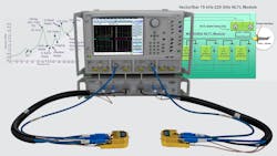
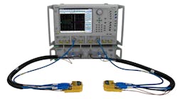
In its VectorStar ME7838G broadband vector network analyzer (VNA), Anritsu has taken a big step toward filling the void in mmWave device characterization (Fig. 1). The ME7838G is the industry’s first VNA capable of making measurements from 70 kHz to 220 GHz in a single sweep, enabling engineers to characterize devices more accurately and efficiently over a much broader range of frequencies. This means more accurate S-parameter device models, thus optimizing the chance for accurate simulations and opportunities to reduce design turns.
The Rising Tide of Frequency
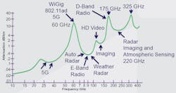
Why do engineers need a broadband 220-GHz VNA? As the communications industry migrates more firmly into the mmWave bands, the need for characterization at higher frequencies becomes apparent (Fig. 2). For example, within the 60-GHz range are Wi-Fi, WiGig, and other ISM types of applications. A 70-GHz broadband VNA will allow you to make measurements within that fundamental band. But if you want to sweep your amplifier to the third harmonic, you’ll need to reach 180 GHz. The fifth harmonic of 5G takes you to the 190-GHz range.
Truly accurate on-wafer characterization of the devices that make up a mmWave IC—amplifiers, mixers, filters, transmission lines, and so on—demands testing of the devices over a frequency range that exceeds their operating-frequency range. VNAs have traditionally been limited in their frequency ranges by the coaxial cables and connectors that access the device under test (DUT). The VNA itself has a broadband frequency range that’s combined with waveguide bands to reach higher in frequency.
Consequently, an important element in Anritsu’s push toward broader frequency coverage revolves around advances in connector technology. Some years ago, Anritsu started down this path when it pioneered the 40-GHz, 2.92-mm connector. The 1.85-mm connector reached the 70-GHz milestone, and a 1-mm connector allows a VNA to sweep frequencies to about 110 GHz.
Therefore, to get to as high as 220 GHz, engineers might employ a concatenated waveguide-band approach. A VNA that operates to 110 GHz with a 1-mm coaxial connector could be paired with a frequency extender with a D-band waveguide to span up to about 170 GHz, followed by more testing with another frequency extender using a WR5 waveguide that covers from 140 to 220 GHz.
While such an approach may work, it brings the headaches of having to calibrate each setup along the way. There’s wear to the aluminum on-wafer landing pads, calibration structures, and probes, which reduces repeatability and uncertainty in test results. And, with different calibration standards often in play, successful de-embedding of the test setup becomes more difficult. With a true broadband VNA (dc to maximum frequency), the user realizes more consistent de-embedding, less calibration issues, and fewer wafer touchdowns.
Pulling it Together
In the VectorStar ME7838G VNA, several strands of technical achievement are woven together, resulting in an instrument that pushes broadband mmWave testing directly to 220 GHz. First and foremost is Anritsu’s nonlinear transmission-line (NLTL) sampling technology—it first appeared in the company’s 110-GHz VNA but is used here to even greater effect. NLTL technology, combined with distinctive circuit layout, delivers important benefits.
Its small, tightly integrated packaging enables direct connection to the test probes for stability and performance. In addition, the circuit’s layout provides optimum raw directivity. As shown in Figure 3, a direct dc-path transmission line goes from the VNA to the test port. The waveguide bands are coupled to that transmission line. Optimum raw directivity lends itself to overall calibration stability that won’t be affected by temperature changes or mechanical flexing of cables.
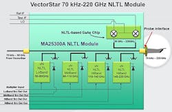
Anritsu’s NLTL technology provides very high conversion efficiency and a very low noise floor, translating to excellent system dynamic range at mmWave frequencies. The new module adds a mmWave source band for frequencies from 140 to 226 GHz. Meanwhile, an NLTL-based harmonic sampler converts test and reference signals to IF from 30 to 226 GHz; that sampler is physically located close to the probe interface.
Before all of that, of course, is the interface with the DUT. Anritsu’s emphasis on connector technology has brought it to the airline-equivalent 0.6-mm level for this instrument, using a slotted sub-0.4-mm male pin center conductor and a slot-less sub-0.4-mm female center conductor. The UG-387 flange provides alignment for the connection, which eliminates the need for a threaded connector. It’s said to be far more repeatable than a coaxial connection that, due to thread wear over time, would see alignment degradation.
Anritsu partnered with MPI to develop the field-replaceable, 220-GHz MPI Titan probes, which are available in pitches of 50, 75, and 100 µm. An important element of the probe’s design is good visibility of the tips for accurate, repeatable on-wafer touchdowns.
About the Author

David Maliniak
Executive Editor, Microwaves & RF
I am Executive Editor of Microwaves & RF, an all-digital publication that broadly covers all aspects of wireless communications. More particularly, we're keeping a close eye on technologies in the consumer-oriented 5G, 6G, IoT, M2M, and V2X markets, in which much of the wireless market's growth will occur in this decade and beyond. I work with a great team of editors to provide engineers, developers, and technical managers with interesting and useful articles and videos on a regular basis. Check out our free newsletters to see the latest content.
You can send press releases for new products for possible coverage on the website. I am also interested in receiving contributed articles for publishing on our website. Use our contributor's packet, in which you'll find an article template and lots more useful information on how to properly prepare content for us, and send to me along with a signed release form.
About me:
In his long career in the B2B electronics-industry media, David Maliniak has held editorial roles as both generalist and specialist. As Components Editor and, later, as Editor in Chief of EE Product News, David gained breadth of experience in covering the industry at large. In serving as EDA/Test and Measurement Technology Editor at Electronic Design, he developed deep insight into those complex areas of technology. Most recently, David worked in technical marketing communications at Teledyne LeCroy, leaving to rejoin the EOEM B2B publishing world in January 2020. David earned a B.A. in journalism at New York University.
