Pulling Back the Curtain on Frequency-Selective-Surface Fabrics
What you’ll learn:
- What are frequency-selective surfaces?
- What comprises these surfaces?
- Maintaining RF performance, particularly in flexible wearables.
Demand for broadband high-data-rate communication continues to escalate. Our use of mobile devices and wireless internet applications for work and entertainment adds fuel to that fire, as does the increasing number of devices interconnected via Wi-Fi, Bluetooth, and the Internet of Things (IoT).
When wireless communication devices must operate in a physically crowded area, such as an apartment complex with multiple households streaming media and working from home, signals become more vulnerable to unwanted electromagnetic interference (EMI) from other devices and wireless systems. Invisible electromagnetic waves from your neighbors may "trespass" into your home, interfere with your systems, and congest the signals.
Such unwanted radiation reduces the signal-to-noise ratio of your wirelessly connected devices, resulting in degraded performance. To get better reception, your wireless router may need to be reconfigured to use a different channel frequency, which can be an inconvenient task.
A better solution to these problems is to make small but clever changes to living spaces and work environments. Just as indoor environments are protected from excessive heat, cold, and moisture, they also can be protected from EMI. In fact, you can treat a space in a way that selectively blocks undesirable signals and only lets the wanted signals through—and it can even be done in a way that’s aesthetically pleasing.
EMI Protection with Frequency-Selective Surfaces
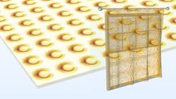
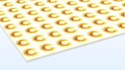
To achieve shielding from EMI, we can utilize frequency-selective surfaces composed of periodic structures (Fig. 1). Such periodic structures have been studied extensively for military applications with the goal of reducing the radar cross section (RCS) of scatterers like radomes, vehicles, and airplanes.
Recently, periodic structures have been the subject of research as a means of enhancing the performance of antenna arrays by suppressing surface waves and improving bandwidth. Researchers also have investigated periodic structures as a way of manufacturing engineered materials, or so-called “metamaterials.” They have permittivity and permeability properties at the macroscopic level that can’t be achieved using traditional materials. Now let’s look at how future applications of frequency-selective surfaces may improve everyday life.
It’s possible make wearable RF and microwave devices and antennas from conductive fabrics. They can be designed to perform reasonably well, even when applied to clothing, where the surface of the component is warped. Frequency-selective surfaces can be woven using fabric and threads like that of regular fabric but made from a conductive material.
If a conductive pattern is printed on the walls, ceiling, or floor of a room, then it’s also able to serve as a bandpass filter or Faraday cage, selectively shielding incoming and outgoing radiation. Similarly, a conductive fabric used as a curtain would be able to (selectively) shield a window.
Avoiding RF Performance Degradation
The biggest challenge when using flexible wearable components (for example, a printed flexible RFID tag) is that it’s hard to maintain the RF performance when the dominant polarization is parallel to the printed surface. Due to the electromagnetic boundary conditions according to Maxwell's equations, the electric field is canceled out when the polarization is parallel to an adjacent conductive body. The device doesn’t perform as in free space unless it’s properly designed with a ground plane and a phase-compensating structure, like a thick, high-permittivity material.
However, when the frequency-selective surface is oriented approximately perpendicular to the direction of incident-wave propagation and matched to the given polarization without being surrounded by RF-opaque materials (e.g., a curtain covering a window), the RF performance problem is no longer significant.
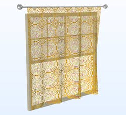
If we assume that the walls in a house are built with metal beams, and that there’s a lossy material finish on the surfaces of the walls with a high dielectric constant, then this structure would be an efficient electromagnetic shield. Incoming waves would, in this scenario, propagate only through the windows. A window is the most appropriate place to hang a frequency-selective-surface fabric because it would simultaneously block sunlight and unwanted electromagnetic signals (Fig. 2).
A window is quite a small portion of most houses. Yet, it’s an electrically large object in terms of the number of wavelengths covered. Numerical analysis of an electrically large device is very computationally intensive both in terms of time and memory. Fortunately, typical frequency-selective surfaces have a repeating pattern that can be exploited to reduce the computational burden.
When a repeating pattern can be identified in an electromagnetic analysis, such as in this case, the whole curtain doesn’t have to be analyzed when calculating its reflection and transmission characteristics. Using the RF Module, an add-on to the COMSOL Multiphysics simulation software, only a unit cell needs to be modeled using so-called Floquet periodic boundary conditions. It includes the interaction between adjacent unit cells and can be used to represent a pattern corresponding to an infinite array of unit cells.
Analyzing Electromagnetics
Now let’s look at a basic electromagnetic analysis of a model that represents only waves with normal incidence to the periodic pattern (Fig. 3). The reflection and transmission characteristics in the frequency domain are, in this case, computed using port boundary conditions. These excite or terminate the simulation domain with a field consisting of a user-defined plane-wave mode. Perfectly matched layers, which are used to absorb any higher-order modes, support the port boundary conditions.

All metallic patterns are modeled as perfect electric conductors, since the loss is expected to be negligible in the simulated frequency range. The shape of the frequency-selective surface pattern is then tuned to transmit only the desired GPS signals, specific band of a cellphone spectrum, Wi-Fi, and Bluetooth frequency ranges. Let’s assume that the frequency-domain study is performed between 1 and 3 GHz.
A plot of the computed S-parameters (Fig. 4) shows the bandpass character around GPS, Wi-Fi, Bluetooth, and partial cellphone bands for UMTS and LTE. The frequency-selective-surface curtain permits the signals in these frequency bands to pass through while reflecting electromagnetic waves for other undesired frequencies.

This simulation prototype demonstrates the feasibility of utilizing a frequency-selective-surface fabric in a living space. There’s plenty of room for improvement, especially with respect to shielding in other frequency bands, which isn’t addressed in this prototype model.
At each frequency band of interest, a certain part of the conductive pattern acts like a resonator. A resonant part is shown in visualizations as an electrically "hot area" in terms of the electric-field magnitude (Fig. 5). Once identified, such an area of the design can be further tuned to enhance the frequency-spectra performance. In addition, the model can be extended for obliquely incident waves as well as for warped fabrics.

Author's note: During my career as a simulation engineer, I long held this idea about modeling a frequency-selective-surface fabric, but it wasn’t realized until I had a chance to visit India. Before traveling to India for the COMSOL Conference and other presentations, I visited several famous cultural heritage sites. In the end, it was an Indian trellis pattern that inspired the frequency-selective-surface model featured in this article.
About the Author
Jiyoun Munn
Technical Product Manager, COMSOL Inc.
Jiyoun Munn is the technical product manager for the RF Module at COMSOL, and a senior member of IEEE. He has two decades of experience in the RF industry, developing over 150 antenna and microwave device prototypes. Munn also holds patents for antenna interrogation systems. He received his MS degree in electrical engineering from the University of Michigan.
