Time-Domain EM Simulators Optimize Automotive Radar

By identifying and mitigating board-level parasitics and variations using finite-difference time-domain (FDTD) electromagnetic (EM) simulation techniques, engineers can raise the performance of automotive radar while improving transportation safety. These EM simulations can benefit RF board, sensor, and fascia-level design by using graphics-processing-unit (GPU) enhancement technology. This approach promises to reduce weeks and days of simulations to a matter of hours. REMCOM provides insight into the use of time-domain techniques with automotive radar in the application note, “Benefits of Time-Domain Electromagnetic Simulation for Automotive Radar.”
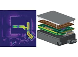
The document reviews the simulation of a multilayer PCB board containing both radiating elements and feed structures. At 25 and 77 GHz, analysis is performed on the parasitic coupling between conductors, current distribution on groundplanes, and the effects of secondary sources [i.e., the local oscillator (LO) line]. To meet original equipment manufacturer (OEM) specifications, the complete sensor system needs to be analyzed for performance and degradation factors—including the case covered with a radome. The note discusses the FDTD simulation of the RF board, radome, packaging, data connector, sensor case, and digital board.
The simulation uses a parameterized geometry of the radome structure to enable its optimization, as the radome significantly impacts the antenna array sensor. In a lab situation, the note details that multiple radome structures would have to be fabricated and measured for performance. The simulation setup, in contrast, only takes a few minutes. Factors like paint color, brackets, and curves in the fascia are also included, as they may affect the antenna’s behavior. To mitigate these concerns, the position of the antenna array relative to the fascia can be parameterized.
Understandably, including all of these features will increase the complexity of the simulation, and thus the calculations necessary to complete it. The note provides random-access-memory (RAM) usage and runtime results for simulations with just the RF board, the RF board/sensor, and the complete system. Because the RAM and run-time requirements would be prohibitive using just central-processing-unit (CPU) technology, NVIDIA GPUs with the Kepler architecture are used to enhance simulation speed by up to 50 times.
REMCOM, 315 S. Allen St., Ste. 416, State College, PA 16801
About the Author
Jean-Jacques DeLisle
Jean-Jacques graduated from the Rochester Institute of Technology, where he completed his Master of Science in Electrical Engineering. In his studies, Jean-Jacques focused on Control Systems Design, Mixed-Signal IC Design, and RF Design. His research focus was in smart-sensor platform design for RF connector applications for the telecommunications industry. During his research, Jean-Jacques developed a passion for the field of RF/microwaves and expanded his knowledge by doing R&D for the telecommunications industry.
