Comparing Automotive Radar RF Bandpass Filter Implementations (Part 2)

Members can download this article in PDF format.
What you’ll learn:
- How planar filter technologies compare for mmWave applications.
- Specific applications of the mmWave filters in the automotive industry.
- Design procedures for mmWave planar filters.
In Part 1 of this multi-part series, we analyzed 3D electromagnetic (EM) simulations in the frequency domain of two of six implementations of a 5th-order, Chebyshev-type RF front-end bandpass filter for automotive radar applications. These involved the mmWave band from 76 to 81 GHz. Those implementations were rectangular metallic waveguides with H-plane iris and cylindrical posts, respectively. In Part 2, we continue our analyses with microstrip and stripline implementations.
Microstrip Type on Rogers RO3003G2
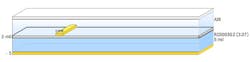
The next subject to tackle in our exploration of 3D EM simulations of bandpass filters is a microstrip design. The dielectric material used is Rogers RO3003G2 PTFE laminate with a thickness of 127 µm. The filter’s layer stackup is shown in Figure 1, while its 2D geometry is shown in Figure 2. The total length of the filter is 4.1 mm.
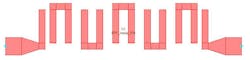
Of the various types of microstrip bandpass filters, the hairpin filter is one of the most common. Its concept is the same as parallel-coupled, half-wavelength resonator filters. The advantage of a hairpin filter over end-coupled and parallel-coupled microstrip is how little space it consumes due to the folding of the half-wavelength resonator. Also, the hairpin design is simpler compared to the other types of microwave filters. The design methodology for this filter is well established.1,2
The simulation was run on a 2.5D electromagnetic solver in the time domain. In doing so, we accounted for metal thickness as well as coupling between all combinations of the coupled lines. To achieve the 50-Ω terminations at the input/output ports, our model incorporated proper tapering (Fig. 2, again). Further, to simplify the optimization procedure, all resonator lines are assumed to have the same width. We also accounted for key design rules of the PCB fabrication houses, such as minimum conductor width and minimum coupled line spacing, so that the design is realistic and able to be fabricated.
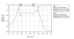
The filter’s RF performance is shown in Figure 3. Due to the dielectric losses of the material used for fabrication and to radiation losses, the quality factor of this filter implementation isn’t as good as that of the metallic waveguide cases discussed in Part 1 of this series. It’s also why this stripline implementation’s selectivity doesn’t have the efficacy of those in the previous cases.
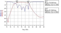
Insertion and return loss exhibit medium performance for the same reasons. The maximum attenuation is 48 dB at 70 GHz and 44 dB at 90 GHz. The performance could be slightly RF-optimized by using Rogers RT5880 Duroid material instead of RO3003G2, but while the former has lower dielectric losses, radiation losses would be about the same. The disadvantage of using RT5880 is its higher fabrication cost as well as the larger filter footprint—its dielectric constant is 2.2 compared to 3.0 for RO3003G2.
Stripline Type on RO3003G2
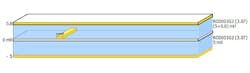
Next, we turn to a stripline design approach using the same RO3003G2 dielectric material as in the microstrip case, but with a total thickness of 254 µm and filter length of 4.1 mm. The main reason for doubling the dielectric layer’s thickness is to enable fabrication of the filter’s physical layout. The procedure used is like the previous microstrip case.1,2 The layer stackup, 2D geometry, and RF performance are depicted in Figures 4, 5, and 6, respectively.
Due to the fact we have a radiation-shielded fabrication technology in this case, the radiation losses are minimized compared to the previous microstrip example. The dielectric losses remain the same. From the RF performance of S-parameters shown in Figure 6, it’s obvious that the frequency selectivity of this filter implementation is far better than that of the microstrip implementation. This is also true for the insertion and return losses. The maximum attenuation is 35 dB at 70 GHz and 48 dB at 90 GHz. Once again, RF performance could be a bit better if we used RT5880 Duroid material for the dielectric.
In Part 3 of this series, we will continue with simulation and analysis of substrate-integrated waveguide (SIW) filter implementations based on an H-plane iris and cylindrical posts and wrap up with conclusions.
Acknowledgement
The author wishes to acknowledge the staff of the School of Electrical and Electronics Engineering, WAVECOMM Laboratory of the University of West Attica for their support in preparing these articles.
References
1. Prof. (Dr.) Sudhir Kumar Sharma, Sandeep Bhullar, Nilesh Kumar, Saurabh Chauhan. Design and simulation of compact hairpin band pass filter, Girraj Sharma, International Journal of Modern Communication Technologies & Research (IJMCTR), ISSN: 2321-0850, Volume 2, Issue 4, April 2014.
2. Abhay Purohit, Sandeep Toshniwal. Design and simulation of hairpin band pass filter for different substrate, International Journal of Engineering and Technical Research (IJETR), ISSN: 2321-0869, Volume 3, Issue 1, January 2015.
About the Author
Dr. Yorgos E. Stratakos
Faculty of Engineering, Department of Electrical and Electronic Engineering, University of West Attica
Yorgos E. Stratakos earned his diploma in Electrical and Computer Engineering in 1992 from National Technical University of Athens, and his PhD degree from the same university in 1995. He is a senior researcher on the faculty of Electrical and Electronics Engineering of the University of West Attica. His main research interests are RF and microwave design of analog passive and active circuits and systems.
