Comparing Automotive Radar RF Bandpass Filter Implementations (Part 1)

Download this article in PDF format.
What you’ll learn:
- How planar filter technologies compare for mmWave applications.
- Specific applications of the mmWave filters in the automotive industry.
- Design procedures for mmWave planar filters.
Automotive radars are frequency-modulated, continuous-wave (FMCW) radars that perform both speed and position measurements of either moving or stationary targets. In the automotive industry, this concept took root in the late 1970s, when early radars of this type were bulky and costly due to their reliance on metallic waveguide technology. Over the last two decades, with the advancement of integrated circuits fabricated on BiCMOS, SiGe, InP, GaAs, and other III-IV technologies, the cost, size, and weight of automotive radar dropped rapidly.
As can be seen from the schematic of a typical RF front-end radar sensor system (Fig. 1), a very phase-stable sawtooth generator drives a millimeter-wave (mmWave) voltage-controlled oscillator (VCO). The oscillator’s output feeds a power amplifier ahead of the transmit antenna. After arriving at the receive antenna, the echo signal is mixed with the original VCO signal to produce the “beat” signal at IF frequency, which is further amplified and processed by means of either analog or digital circuitry.
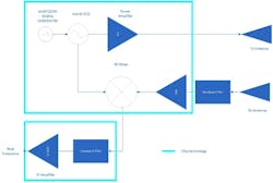
The components surrounded by the light-blue rectangles in Figure 1 are typically integrated in a single chip nowadays. Often integrated antennas are included on the same chip. Many times, antennas aren’t single components; rather, they’re antenna arrays with beamforming capabilities to track the targets more efficiently.
A key RF component in Figure 1 is the bandpass filter at the receiver side, which blocks any unwanted signals outside the mmWave frequency range of 76 to 81 GHz. Even though the bandpass filter at the input of the receiver will degrade the receiver’s sensitivity by an amount equal to its insertion loss, it’s strongly advised to be placed as shown in Figure 1, where it rejects unwanted (interfering) signals and thus improves the linearity of the whole receiver chain.
In this series of articles, we’ll present a comparative analysis of the filter RF performance as fabricated on various technologies. The filter can be realized in either planar or 3D technologies, but some key aspects must be considered such as insertion loss, out-of-band rejection, and form factor. To investigate the RF performance of different technology implementations, we performed our comparisons using 2.5D and 3D electromagnetic (EM) simulation of highly detailed models.
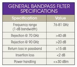
For each of the implementations, the general filter specifications2 are shown in the table.
To achieve the filter-rejection specifications for the automotive radar system,2 we chose to implement the filter as a 5th-order Chebyshev type developed on different technologies:
- Rectangular metallic waveguide with H-plane iris
- Rectangular metallic waveguide with cylindrical posts
- Microstrip type on Rogers RO3003G2 PTFE laminate, h = 5 mils
- Stripline type on RO3003G2, h = 10 mils
- Substrate integrated waveguide with H-plane iris (RO3003G2, h = 5 mils)
- Substrate integrated waveguide with cylindrical posts (RO3003G2, h = 5 mils)
This article series will present 3D electromagnetic simulation results for each of the above technologies and compare their respective filter performance, fabrication costs, ease of implementation, and so on. The sections below present the 3D electromagnetic simulation results as well as the general design procedure for the first two bandpass-filter implementations: rectangular metallic waveguides with H-plane iris and cylindrical posts, respectively.
Rectangular Metallic Waveguide with H-plane Iris
In this implementation, the waveguide consists of a hollow metal block that guides the electromagnetic waves. Because the electric field and a magnetic field are bounded by its walls, there’s no power loss through radiation and dielectric losses are negligible as the waveguide is typically filled with air.
In the lossless waveguide, some differences exist between transverse-electric (TE) and transverse-magnetic (TM) modes.5 In TE modes, the electric field (E-field) travels perpendicular to the direction of propagation and the magnetic field (H-field) travels in the same direction as the propagation. In TM mode, the magnetic field travels perpendicular to the direction of propagation and the electric field travels in the same direction as propagation.
The dominant mode in a rectangular waveguide is TE10.5 Electromagnetic-wave propagation in the waveguide can occur in several modes; the dominant mode is a mode that has the lowest cutoff frequency. The cutoff frequency for a rectangular waveguide is determined by Equation 1:6
fc = (1/µ × ε) × √[(m/a)2 + (n/b)2] (1)
where:
a = inside width (m)
b = inside height (m)
m = waveguide mode number
n = waveguide mode number
ε = permittivity for free space (8.854 × 10⁻¹²) in farads per meter
μ = permeability of free space (4π × 10-7) in henries per meter
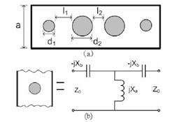
Figure 2 depicts the equivalent circuit of the 5th-order Chebyshev filter using an H-plane iris.6

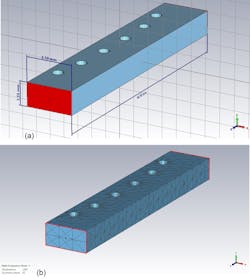
The design procedure for filters of this type is well-established and described in detail in various books.5,6 In this approach, proper machining of an aluminum block provides the metallic iris to form the metallic waveguide filter.4 The dimensions of the waveguide port are those of a WR12 waveguide (a = 3.1 mm, b = 1.55 mm). The total length of the filter is 15.6 mm, while the metal insert thickness is 0.5 mm.
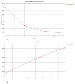
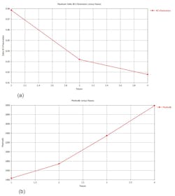
To be as close as possible to the real world, the 3D-simulated iris is curved with a radius of 0.25 mm, where the iris touches the waveguide walls. We simulated the filter in the frequency domain using a commercial 3D simulator with convergence criterion such that the S-parameter change in the successive meshing steps should be less than 2%. Figures 3a and 3b plot the adaptive convergence metrics.
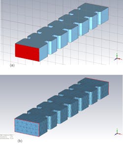
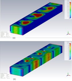
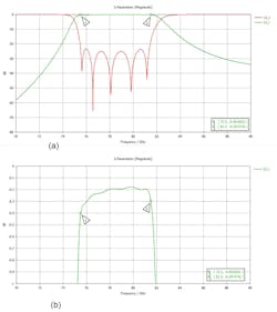
The 3D geometry is shown in Figure 4a, and Figure 4b shows the meshing volume used for the frequency-domain 3D simulation. The basic dimensions also are given in Figure 4. The electric and magnetic fields’ distribution at center frequency of 78.5 GHz is shown in Figure 5. Figure 6 illustrates the RF performance of the iris-based waveguide filter (a) with the detailed insertion loss (S21) shown in the filter’s passband (b).
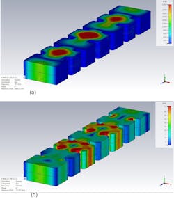
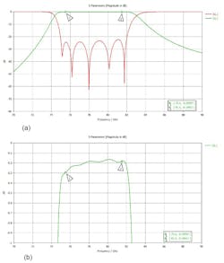
Return loss in the passband is better than 22 dB and insertion loss is better than 0.3 dB. Rejection at 70 GHz is greater than 48 dB, while at 90 GHz it’s greater than 32 dB.
Rectangular Metallic Waveguide with Cylindrical Posts
To fabricate a rectangular metallic waveguide with cylindrical posts, one would machine an aluminum brick so that the dimensions of the waveguide port are those of a WR12 waveguide (a = 3.1 mm, b = 1.55 mm). The total length of the filter is 16.8 mm, while the metallic-post diameter is 0.75 mm. In general, the metallic posts needn’t be identical—Figure 7 shows the general approach. The equivalent electric circuit diagram is a T-network consisting of series capacitances and a shunt inductor.7 The geometric parameters are derived from well-known textbooks.6
We simulated the post-based filter in the same fashion as the iris-based implementation described above. Figure 8 displays its adaptive convergence metrics, while Figure 9 shows its 3D geometry and meshing volume used for the frequency-domain 3D simulation (as well as basic dimensions). Figure 10 depicts the electric and magnetic fields’ distribution at center frequency of 78.5 GHz.
In Figure 11, we see the RF performance of the post-based filter along with the detailed insertion loss (S21 parameter) in the filter’s passband.
Return loss in passband is better than 22 dB and insertion loss is better than 0.3 dB. Rejection at 70 GHz is greater than 55 dB and at 90 GHz it’s greater than 32 dB.
In Part 2 of this series, we will continue with simulation and analysis of the microstrip and stripline filter implementations.
Acknowledgement
The author wishes to acknowledge the staff of the School of Electrical and Electronics Engineering, WAVECOMM Laboratory of the University of West Attica for their support in preparing these articles.
References
1. Maria S. Greco, Automotive Radar, Dept. of Information Engineering, University of Pisa, 2012 IEEE Radar Conference, May 7-11, Atlanta.
2. ETSI EN 301 091-1 v2.1.1 (2016-11)
3. Dr. Alois Ascher, “Automotive Radar Performance Characteristics,” Rohde & Schwarz
4. Sri Hardiati, Sulistyaningsih, “The design of waveguide band pass filter with double-irises structure for airport surveillance radar applications on S-band frequency,” Topic Teguh Estu, AIP Conference Proceedings 1755, 170010 (2016).
5. S. Y Liao, Microwave Devices and Circuits, Prentice Hall, New Jersey, 2009.
6. G. L. Matthae, L. Young, and E.M.T Jones, Microwave Filter, Impedance Matching Network, And Coupling Structures, McGraw-Hill, New York, 1964.
7. Woon-Ci Yeo et al, “H-Plane Sectoral Filtering Horn Antenna in PCB Substrates Using Via Fences at Millimetre Wave,” Korea Aerospace University, conference paper, EUMC 2007.
About the Author
Dr. Yorgos E. Stratakos
Faculty of Engineering, Department of Electrical and Electronic Engineering, University of West Attica
Yorgos E. Stratakos earned his diploma in Electrical and Computer Engineering in 1992 from National Technical University of Athens, and his PhD degree from the same university in 1995. He is a senior researcher on the faculty of Electrical and Electronics Engineering of the University of West Attica. His main research interests are RF and microwave design of analog passive and active circuits and systems.
