Keep Abreast of RF Filtering Trends (Part 1)

Download this article in PDF format.
What You’ll Learn:
- The tasks performed by filters in various RF architectures.
- Differentiating factors between those architectures.
- Current trends in filter performance considerations.
At any given time, a multitude of signals at various frequencies are streaming all around us. Devices such as televisions, radios, radars, medical devices, and cell phones rely on receiving the proper RF signal to deliver what’s expected by the end user. Therefore, each of these devices requires some level of filtering to attenuate or remove unwanted signals from the desired channel. Without filtering, these devices can become saturated and unwanted signals can combine with desired signals to corrupt information.
While all filters have the same basic job—to remove unwanted or out-of-band signals—the specific job requirements of each filter vary depending on the given RF architecture and needs of the target device. In addition, the need for filtering is frequency-agnostic. While there’s an overall trend for RF devices to operate at higher frequencies across applications, especially in the mobile telecom industry, it’s not the requisite filtering jobs that are changing as much as the technologies needed for filtering at these higher frequencies.
An Overview of Filtering Jobs Across RF Architectures
When designing a filter for an application that depends on receiving and sending RF signals, the first step is to identify the jobs that must be performed by the filter. These jobs can be very different depending on the RF architecture used in the application. Let’s examine filtering tasks in three common RF architectures—superheterodyne (superhet), direct conversion, and direct sampling.
The superhet architecture is well-established and offers high performance over a wide range of frequencies, which makes it one of the most widely used radio receivers today. In this architecture, frequency mixing converts a received signal to a fixed intermediate-frequency (IF) signal to simplify processing (Fig. 1).
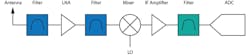
Multiple RF filters take on several challenges in the superhet architecture, including:
- Preselection: A bandpass filter selects the spectrum range that contains the band of interest, allowing only the desired RF frequency to pass while suppressing the undesired spectrum.
- Removing image spurs: These are RF signals outside the band of interest that could mix with the LO and generate tones in the IF signal.
- Removing IF spurs: This is RF energy at the IF frequency that can show up as a tone in the IF.
- Removing LO leakage: This is radiation from the LO that can pass up and down the receiver chain. LO leakage could cause problems for the receive function as well as potential emission problems from the receiver itself.
While the superhet architecture is a proven and trusted approach, the large component count can impact size, weight, and power (SWaP), making it an impractical option for some RF applications. Therefore, in contrast to a superhet, a direct-conversion receiver (DCR)—also known as a homodyne, synchrodyne, or zero-IF receiver—doesn’t need to convert incoming signals to an IF signal. Instead, a DCR uses an LO with a frequency that’s close to identical to the carrier frequency to demodulate the incoming signal via synchronous detection and generate the final baseband input to the analog-to-digital converter (ADC) (Fig. 2).
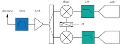
In a DCR, the RF filter’s jobs include preselection; preventing out-of-band signals from saturating the analog front end; and aliasing, which can be handled by a low-pass filter at baseband. This architecture is a good fit for applications that must maximize ADC bandwidth and need simplified wideband options from a SWaP standpoint. However, the need for I/Q balance and image rejection, and the potential for in-band harmonics, can make a DCR challenging to use in some applications.
Finally, the newest of these receiver architectures, the direct-sampling variety, is perhaps the holy grail of receiver architectures from a component simplicity standpoint. In direct sampling, the incoming signal is filtered to provide some selectivity and then amplified in an LNA with no mixing involved. Lastly, the RF signal is directly sampled by a fast ADC into digital form (Fig. 3).
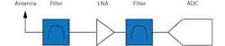
The jobs required of filters in a direct-sampling approach are like the jobs done in a DCR. They include preselecting, preventing out-of-band signals from saturating the analog front end, and aliasing with a bandpass filter to prevent interference in the alias bands of the ADC. While direct sampling is a great option from a SWaP perspective, the approach presents some challenges, including bandwidth limitations by the ADC bandwidth at RF and the potential for gain imbalance.
Trends in Filter Performance Considerations
Once the general job of a filter is determined based on the architecture at hand, it’s time to think more specifically about the performance requirements for the filter based on the application it’s being placed in. Let’s look at a few industry-wide trends impacting filter performance decisions today.
Trend 1: It’s not just about your application’s current operating frequency.
As mentioned, the need for filters is frequency-agnostic—whether you’re working on an electronic warfare system at 8 GHz or a 5G millimeter-wave (mmWave) system at 28 GHz, you’ll need some level of filtering. Because no filter can operate across all frequencies, the appropriate filter for your application changes depending on if it’s functioning at the low or high end of the spectrum (Fig. 4).

But today, there are several reasons why it’s not enough to simply consider the band your device is currently operating in. For example, let’s look at mobile devices. One overarching trend is the shift to 5G. Currently, the 5G operating spectrum is divided into two frequency ranges—FR1, which covers 4.1 to 7.125 GHz and spans the L, S, and C bands; and FR2, which covers 24.25 to 52.6 GHz and includes the Ka band and beyond.
Because the availability of these bands is managed differently by region depending on where your end device will be used, the spectrum environment, or which frequencies are interacting with the band of interest, may change. How are operating frequencies managed in the United States? The Federal Communications Commission (FCC) holds auctions in which commercial concerns may purchase available frequencies. Table 1 shows a list of recent and upcoming auctions.

Companies should be prepared to have different filtering requirements depending on which operating frequencies they purchased. In addition, their filter considerations will also change based on the type of applications operating at adjacent frequencies.
As more frequencies become available for devices to operate on, this trend of considering what’s operating nearby gains more steam. For example, Earth Exploration-Satellite Services (EESS) operate globally between 23.6 and 24 GHz, which is directly adjacent to the 5G n258 band that operates between 24.25 and 27.5 GHz.
To prevent interference with the EESS, the International Telecommunication Union (ITU) placed limits on how much radiation may “leak” from 5G operations into the EESS band. Therefore, filters used in 5G devices operating at 24.25 GHz need high selectivity. This can be simplified if the filter technology is inherently high Q, which can also have the added benefit of reducing the complexity of the filter design required to reach a selectivity target.
Furthermore, in 2021, the 3.5-GHz band will be reallocated from military to telecom applications. As a filter designer, keeping an eye on trends, such as what is coming next in terms of available bandwidth, is important for being prepared to meet future filter needs.
Trend 2: Miniaturizing devices while also improving tolerance.
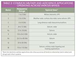
In general, depending on where RF filtering is deployed in the architecture, space will come at a premium. Like most industries, the trend in military and aerospace is to extend capabilities, such as rapidly sending and receiving more data, with a smaller footprint. Thus, more communication technology is being crammed into each satellite, which means the demand for smaller and lighter components is trickling down the supply chain.
Concurrently, in response to the ever-increasing demand for communications via satellite, satcom designers are pushing past the X and Ku bands to the higher-frequency Ka and V bands (Table 2). As a result, there’s a trend to shift from traditional heterodyne architectures to a direct RF sampling approach, which inherently changes the filtering tasks.
Considering the importance of reducing mmWave filter size to keep up with the general trend of device miniaturization, manufacturing tolerance also plays a crucial role. Poor tolerance encroaches on potential board space or layers that could be used to add other devices or functionality. On top of that, tolerance not only affects filter specifications such as planned versus realized performance and potential loss of bandwidth, it also increases the cost of implementation.
In short, at mmWave especially, tolerance impacts can become significant and potentially alter the total cost of an implementation. If tolerance isn’t considered during manufacturing, it can affect the yields of the overall system and further increase the need for guard banding, taking up useful spectrum space.
Trend 3: Managing temperature-stability issues.
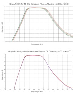
As devices become smaller and denser, it becomes much more difficult to control temperature, which means systems will run hot and frequency variations may occur. Therefore, the emerging trend is for filters to perform within specification over a wide range of temperatures, with temperature stability of approximately 3 ppm/°C. By designing filters with the right dielectric material and filter topology, one may produce temperature-stable surface-mount filters with high rejection and low loss (Fig. 5).
Part 2 of our RF-filtering trends series will address current and emerging technologies that help meet the upcoming challenges in RF design work.
Peter Matthews is Senior Technical Marketing Manager at Knowles Precision Devices (KPD).
About the Author

Peter Matthews
Senior Technical Marketing Manager, Knowles Precision Devices
Peter Matthews is Senior Technical Marketing Manager at Knowles Precision Devices. As a division of Knowles Corporation, Knowles Precision Devices (KPD) focuses on production of a wide variety of highly engineered capacitors and microwave to millimeter-wave components for use in critical applications in military, medical, electric vehicle, and 5G market segments. Peter has over 20 years of experience in technology sales, marketing, and product management.
