Tips for Biasing MMIC Amplifiers
Many monolithic-microwave-integrated-circuit (MMIC) amplifiers are shipped without self-biasing networks. Knowing the process for biasing these devices is therefore essential for building quality microwave devices. Biasing techniques differ for each of the three types of MMIC amplifiers: standard, cascode, and hetrojunction bipolar transistor (HBT). In “MMIC Amplifier Biasing Procedure,” Hittite Microwave discusses the methods for biasing each variety of MMIC amplifier. The application note also describes the setup required to perform successful biasing.
Two types of HBT MMICs are discussed in the paper: self-biased and self-biased with current control. The self-biased HBT MMIC relies on simple collector voltage activation with a bias resistor. That resistor sets the current for the current mirror, which controls the base voltage. The self-biased HBT MMIC with current control requires an external voltage, known as the power-down control voltage. It controls the current of the current mirror and the base voltage. The paper details the exact sequence needed to ensure proper device operation and prevent critical failures in HBT amplifiers.
For the standard amplifier typology, the bias sequence requires a dual supply, which is positive for the drain-source and negative for the gate-source voltage. The gate voltage is critical in adjusting the drain current for optimal amplifier operation. The process for properly biasing the standard amplifier is detailed in the beginning of the application note, which later tackles power supplies at zero and a damaged-part troubleshooting approach.
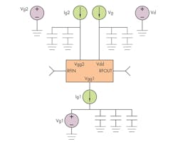
It also discusses a cascade-distributed amplifier with a complex biasing structure. This amplifier requires a positive supply for each gate for the unit cell of two FETs in series. Additionally, the amplifier relies on a negative supply for the gate-source voltage. After all the bias interconnections have been set, the first voltage to increase is the gate-supply voltage from the first transistor in the cascode arrangement. Yet it only increases enough to reach pinch-off drain current. If oscillations are observed, the note recommends adding a resistor in series with the gate line or lines.
Hittite Microwave Corp., 20 Alpha Rd., Chelmsford, MA 01824, (978) 250-3343
About the Author
Jean-Jacques DeLisle
Jean-Jacques graduated from the Rochester Institute of Technology, where he completed his Master of Science in Electrical Engineering. In his studies, Jean-Jacques focused on Control Systems Design, Mixed-Signal IC Design, and RF Design. His research focus was in smart-sensor platform design for RF connector applications for the telecommunications industry. During his research, Jean-Jacques developed a passion for the field of RF/microwaves and expanded his knowledge by doing R&D for the telecommunications industry.
