X-band Push-Push Oscillator Simulation and Measurement (Part 2) (.PDF Download)
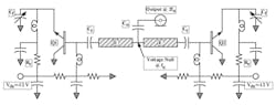
This article continues where Part 1 left off with a discussion of the push-push oscillator topology. The push-push oscillator circuit topology joins two common-collector oscillators at the grounded end of the resonator (Fig. 1). The voltage null of each section of the oscillator becomes the common junction of the push-push configuration, and the coupled transmission line is removed in favor of a simple coupling capacitor.
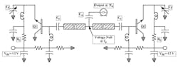
1. This is the push-push oscillator circuit topology. The push-push oscillator is structured from the connection of two common-collector oscillators such that the null point of the circuit is maintained.