The Critical Nature of Quality Coax for Field Testing
Members can download this article in PDF format.
What you’ll learn:
- How RF field testing is evolving in complexity.
- How environmental and mechanical strains affect test cables.
- The impact of coaxial-cable construction on field test.
The test and measurement (T&M) industry offers a bounty of equipment and cables often particularly suited either to laboratory or production test environments. Compared to field testing, benchtop test equipment and cables seem light-duty in nature.
Technicians attempting to perform tower testing with distance-to-fault measurements and site maintenance are faced with tight spaces for mating and unmating. This is further compounded by dynamic environments with inclement weather conditions, let alone moving vehicles and personnel that can expose equipment and cables to extensive UV exposure, high humidity, salt-laden atmospheres, and mechanical strains. Thus, field cables must meet both the high electrical performance requirements found in typical T&M applications with additional parameters that relate to cable ruggedness.
For coaxial cables, it can translate to a low voltage standing wave ratio (VSWR) and attenuation plus precision amplitude and phase stability with flexure, as well as further mechanical ruggedization via cable armoring and the careful choice of cable-jacketing materials. This article looks at the world of RF field tests and the litany of testing parameters and considerations that go into these test practices. The importance of quality components in these fields can’t be overstated as the cost of failed tests may dramatically increase expenditures down the line.
The Evolving Landscape of RF Field Testing
In the realm of cellular infrastructure testing, cellular providers are tasked with supplying the nation with relatively seamless voice quality and, more recently, video streaming. This is a complex task in and of itself. However, complexity has increased with the stringent key performance indicators (KPIs) of 5G. The need for gigabit speeds, low-latency communications, virtually seamless connectivity, and nearly ubiquitous availability makes testing the infrastructure to support these KPIs even more rigorous and more critical.
Much effort has gone into the research and development of next-generation cellular systems with inclusion of the mmWave spectrum and innovation around newer technologies such as small cells and massive MIMO (mMIMO). Engineering and production testing is critical to ensure a level of quality of the equipment before deployment. Field testing directly corresponds to field performance (failure-in-time, or FIT, rates) and long-term wear mechanisms of equipment. All aspects of this testing yield a better perspective on the status of base-station equipment and only contribute to the ongoing evolution of base-station performance.
It’s largely inarguable that the main purpose for testing cellular systems and subsystems is to directly gauge a mobile network operator’s (MNO) cellular performance and ensure a high level of quality of service (QoS). The level of QoS must be maintained even at the extremes of connectivity, such as in dense urban areas, for mobile users (V2X, aircraft, marine, trains, and so on), and in rural areas relying heavily on microwave backhaul. However, this has morphed with the changing architectures of base stations.
The evolution of base-station cables, antennas, and subsystems has shifted substantially. It proceeded from the conventional base-station (BTS) rack transporting information to the multi-port passive antenna with massive installations of feeder coax and a necessary tower-mounted amplifier (TMA) (Fig. 1).
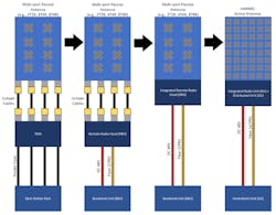
The next evolution involved a remote radio head (RRH) that brought the radio closer to the antenna by handling the conversion between the digital and RF signals via the standardized Common Public Radio Interface (CPRI) protocol. The baseband unit (BBU) at the base of the tower handled the bulk of the processing by providing the physical interface between the base station and the core network.
Now, MIMO antennas often leverage an integrated RRH to bypass the use of jumper coax cables. mMIMO active-antenna system (AAS) structures integrate the transceiver units with each antenna element and integrate the RRH with the AAS.
A Look at Some Field Tests
All of these changes in technology have transformed field-testing methods and apparatus. The cellular subsystems for a typical Evolved Node B (eNodeB) include the TMA, BBU, RRH, and antenna systems, along with their integrated filters, amplifiers, and all interconnected cabling. Having so many components can cause reflections and signal disruptions that result in poor coverage, dropped calls, low data throughput, unnecessary handovers, and access failures on the uplink.
Passive intermodulation distortion (PIM) in passive components such as coaxial connectors, antennas, and isolators can cause high interference levels, particularly for passive and hybrid distributed-antenna-system (DAS) installations. Adjacent channel leakage and co-channel interference also may produce interference. Testing channel power, occupied bandwidth, adjacent channel leakage (ACLR), and spurious emissions with portable instruments for field testing can quickly validate the performance of an existing cellular system.
In addition, the cables themselves may suffer from high attenuation levels, with internal physical imperfections causing much of the signal to diminish by the time it arrives at the antennas. A slight kink in the coax, unraveling of the shielding materials, or swelling of the dielectric materials may induce significant reflections and increase insertion loss. Distance-to-fault (DTF) measurements send signals down the cable length to determine the precise location of the cable fault.
A similar issue can be seen with fiber-optic cables, in which imperfections such as particles, cracks, and surface damage to the optical fibers can cause significant reflection and insertion loss. Installers should be able to rapidly inspect these components to verify their performance. They can use optical time-domain reflectometers (OTDRs) to test attenuations, event loss, reflectance, and optical return loss. Handheld network analyzers allow for frequency-domain (S-parameter) analysis of a coaxial cable, yielding return loss/VSWR and insertion-loss measurements.
The field-test engineer’s toolkit could include base-station analyzers, cable and antenna analyzers, handheld network analyzers, portable spectrum analyzers, OTDRs, fiber-optic inspection equipment, and more. Common analyzers like Keysight’s FieldFox, Anritsu’s Site Master, Viavi’s CellAdvisor, and Bird’s Sitehawk often contain multiple instruments to save time (less calibrations, less equipment to track, and so on) and minimize the learning curve associated with field tests.
Such equipment is geared toward the testing of every aspect of a cellular network. It ranges from the RF characterization and conformance testing of the base station (EIRP, beam analysis, carrier aggregation testing, antenna alignment, ALCR, and more), to the CPRI or eCPRI fronthaul network and connected BBU subsystems, to the Ethernet backhaul network.
How Coax Construction Impacts Test Performance
RF-analysis equipment has almost universally required the use of coaxial cables to connect to the device under test (DUT). That’s because the coaxial transmission line supports the highly desirable transverse-electromagnetic (TEM) mode, in which the E- and H- field components are transverse, or perpendicular, to the direction of signal propagation. It allows for a broad, mode-free bandwidth with an upper cutoff frequency.
To support this mode of propagation, the coaxial cable must have consistent cross-sectional dimensions along the length of the transmission line. In other words, the dimensions of the inner and outer conductors must be consistent. This is where the dielectric “tube” comes into play—it separates these two conductors so that the spacing between them is consistent, making the characteristic impedance the same along the entire coaxial cable.
Most RF tests require a calibration to bring the test plane to the edges of the DUT, which accounts for, and calibrates out, the losses and phase shifts from the test cables. In a typical test, a conventional short-open-load-thru (SOLT) calibration kit will often suffice, with exceptions such as 75-Ω systems, test fixturing, on-wafer probe testing, and the testing of planar transmission lines (e.g., microstrips, coplanar waveguides, and striplines).
Yet, no matter how straightforward the calibration might seem, it’s often necessary to perform a calibration before a test because of ineligible effects of calibration drift, which makes every calibration less accurate. Drift is caused by temperature variations that affect both the internal components of the instrument and the test cables themselves.
Test cables are most susceptible because they’re directly handled by the technician/engineer. Constant bends and flexes will cause slight variations in amplitude, which may contribute to measurement errors over time. Both temperature and bending also impose slight changes in both the mechanical length and dielectric constant (εr), causing phase instability and drift errors.
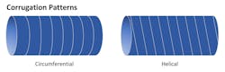
Amplitude- and phase-stable test cables require the use of a phase-stable dielectric material that has undergone temperature cycling. The changes in amplitude and phase due to flexures can be mitigated by simply armoring the cable with a corrugated metal tube. These tubes also can be made for tighter bend radii or more resistance to crushing and torquing by altering the corrugation and interlocking technique (Fig. 2). More complex, interlocked metallic hoses may impose a strict limit on the bend radius of the coaxial cable so that a technician could not bend the cable beyond a certain bend radius.
Impact of Environmental, Mechanical Strains on Test Cables
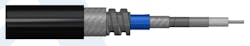
No manufacturing process is ideal. When exposed to potentially harsh environmental conditions and improper handling, a test cable could be rendered useless. The ruggedization of the coaxial cable, such as cable jacketing, armoring, and strain relief, can make or break the cable assembly, especially in outdoor environments (Fig. 3).
Plasticizers are often used in thermoplastics (e.g., PVC, PE, and PTFE) and elastomers (e.g., EPR, PUR, and neoprene) to augment the original material for desirable qualities such as more flexibility, impact strength, or better high-temperature performance. Excessive exposure to UV, moisture, humidity, or chemicals can cause these plasticizers to desorb during the cable’s lifetime. When this occurs, cable jackets are more prone to cracking, swellings, or otherwise exposing the internal transmission line to the elements. This ongoing issue can be avoided with strengthened jacketing material that’s resistant to UV and moisture and can withstand temperature extremes.
Cables also degrade rapidly with mechanical strains such as vibration, mechanical shock, tensile strains, flexure, and crushing, all of which are possible in the dynamic testing environments found in the field. As stated earlier, both the armoring and strain relief are critical in extending the cable’s lifetime. All of these qualities have a direct impact on test time and test accuracy in the field.
While the upfront capital expenditure for ruggedized cabling may be higher, the operating temperature, phase/amplitude stability, and mechanical and environmental resilience all contribute to a lower operating expenditure. That’s because such cables enable tests to be performed more rapidly and without delicate handling.
Understanding the Aspects of a Quality Assembly Process
Cables that require reliability will almost always need a level of trackability. Typically, commercial coaxial cables are batch tested after they’re manufactured and, depending on the lot size and the number of test samples taken from it, quite a bit of quality variation may exist between coax within a lot. This is further exacerbated by the plethora of coax vendors, as the difference in quality between different manufacturers can be substantial.
Most website datasheets will simply list minimum, nominal, and maximum insertion loss and VSWR values within the bandwidth of the coax, along with basic mechanical specifications such as weight, bend radius, cable construction, and operating temperature. An insertion-loss and VSWR graph might illustrate the cables’ frequency response. This, however, often comprises data taken from a singular cable as part of a batch, so it’s more than likely that the data depicted isn’t from the cable purchased, but rather from a sample within the batch.
Ruggedized, high-reliability cables are often serialized to ensure that the product can be tracked back within a manufacturer’s enterprise resource-planning (ERP) system (Fig. 4). It begins with tracking of the base materials going into the coax and follows through with careful monitoring of the assembly process.

A standard verification method is necessary to mitigate any variability in quality. This includes the verification of the solder joints after the installation of each connector, gauging the pin and insulator position of each connector, and the final RF testing specific to the unique cable that was assembled. These tests can go beyond the standard two-port S-parameters and involve phase stability, amplitude stability, power handling, velocity of propagation, and/or dielectric withstanding voltage. Additional mechanical parameters might include flex cycles, mating cycles, and crush resistance.
Conclusion
Ruggedized field-based analysis tools are only as good as the cables that connect them to the DUT. The cables themselves can easily cause these tests to fall out of calibration without amplitude or phase stability. A long cable service life also is necessary in harsh environments where elements such as UV and humidity could rapidly deteriorate the quality of the cable. This is especially critical for the coaxial transmission line given that minor nonconformities and flaws within the coaxial line can lead to undue reflections and loss. In addition, connectors must be handled carefully to mitigate the harmful ingress of dust and moisture.
The handling of coaxial cables isn’t always straightforward in the field. Tight spaces can cause technicians to bend their cables excessively, inducing both amplitude and phase changes and a potential kink in the coax. Durable coaxial construction with layers of protection and armoring mitigates the bending, prevents kinking, and offers a degree of crush resistance to the coax itself. The result: Precise, repeatable measurements that save site maintenance and repair costs in the long run.
About the Author
Peter McNeil
Marketing Manager, Pasternack
Peter McNeil is a marketing manager at Pasternack and has over 25 years of experience in sales development, product management, and marketing in the telecommunications, RF, and microwave industries. He currently oversees the development and delivery of several of Infinite Electronics brands content, including Pasternack.
