Phase Measurements, Calibration Critical in Verifying mmWave Designs
Members can download this article in PDF format.
What you’ll learn:
- How mmWave adoption has impacted VNA applications.
- Fundamentals of various VNA calibration methods for high frequencies.
- The VNA measurement challenges faced by designers in the mmWave bands.
As commercial, military/aerospace, and other communications designs extend into the millimeter-wave (mmWave) spectrum, engineers must adapt their testing procedures and require more from instruments such as vector network analyzers (VNAs). Shorter wavelengths associated with mmWave frequencies place more weight on phase measurements, while also emphasizing the need for proper calibration.
Phase measurements have even gained in importance when verifying passive-component measurements. Phase differences can be very small, depending on the material, so a VNA must measure even the slightest variations. It does so by comparing the incident signal, leaving the analyzer with either the signal that’s transmitted through the device under test (DUT) or the signal reflected from its input.
Influx of mmWave Designs
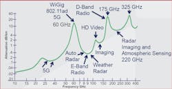
The mmWave band is defined as 30 to 300 GHz with a wavelength between 1 and 10 mm in the air. Its unique characteristics, such as penetration through fog, rain, and cloud, can enable a variety of applications. The wide bandwidth of the mmWave band also makes it very attractive for ultra-high-speed wireless and satellite communications. Figure 1 shows common applications and related frequencies.
But increased frequency is only one part of the equation. Miniaturization of components/devices also adds to the importance of phase measurements in modern designs.
Waveguide Limitations
VNA calibration is crucial when it comes to accurately verifying designs utilizing these technologies. It’s particularly relevant, as mmWave measurements must be conducted over the air (OTA).
Accurate device characterization must sweep from near-dc to well beyond the harmonic frequencies to provide accurate models. Previously, engineers used different waveguides for high-frequency measurements. Waveguides are preferred for power-delivery applications, but there are some drawbacks for higher-frequency designs. One negative is the possibility of incorrectly mating apertures, which will adversely affect repeatability. RF leakage and slower/limited time-domain analysis are additional concerns.
Perhaps the biggest negative for high-frequency designs, though, is that waveguides are band-limited. Thus, engineers must “stitch” the measurements together when verifying their mmWave products. This is time-consuming and reduces accuracy and repeatability. A broadband VNA system can eliminate the need for waveguides by conducting sweeps of the entire range for more reliable modeling.
Calibration Technique
Testing at mmWave frequencies brings new and different measurement challenges. Minimizing measurement uncertainty is critical in the development of these new technologies. Calibration is one way to achieve this goal.
Calibration is essential due to a VNA’s internal structure, as well as external factors that include cables, fixtures, and modules. They all have behavioral characteristics, such as frequency mismatches, that must be corrected to attain accurate measurements. Calibration needs to be done at the DUT end of the cables for the best possible results.
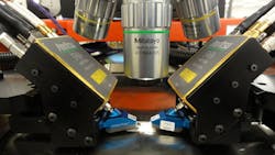
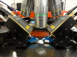
Engineers must perform tedious calibration routines to remove the amplitude and phase effects of those added cables and waveguide from mmWave S-parameter measurements. For these reasons, cables should be avoided at higher frequencies because they pose challenges to calibrating. Fortunately, mmWave modules that don’t require cables have been developed—they improve repeatability and stability by eliminating the need to calibrate the cables (Fig. 2). And, of course, they remove the costs associated with expensive cables.
High-Frequency Calibration Options
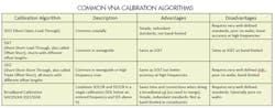
The traditional calibration approach is to use a known standard, such as Short-Open-Load-Through (SOLT) or Short-Short-Short-Through (SSST). Standards compensate for internal losses and enable the device characteristics to be measured. The table shows the calibration algorithms, as well as their advantages and disadvantages.
Calibration techniques leave many uncertainties to be addressed. These include noise floor, trace noise, and residual calibration errors. However, the two most important at high frequencies, such as mmWave, are drift and repeatability.
The SOLT/SOLR (Short-Open-Load-Reciprocal) algorithms are often not recommended for higher frequencies due to the difficulty of fabricating a reasonable open standard beyond 65 GHz. An open waveguide flange radiates quite effectively, which results in instability and a relatively high return loss.
A coaxial open-circuit standard must use an enclosed approach. At the open end of the inner conductor, a frequency-dependent fringing capacitance is formed. Even if an open standard could physically be constructed with zero length, fringing capacitance will occur.
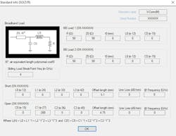
A coaxial short circuit can be constructed with almost ideal characteristics, enabling total reflection of the incident energy. Within the short circuit, there will be a small length offset. In coax, a zero-length short and a perfect shielded open exhibit 180-degree phase separation, while a matched load will provide 40- to 50-dB magnitude separation from the short and open. Figure 3 shows the standard information provided by the SOLT/SOLR calibration algorithms.
For waveguides, the SSST/SSSR (Short-Short-Short-Reciprocal) approach is recommended at higher frequencies because a load standard isn’t required. Accurate knowledge of the short offset lengths also is critical.
New calibration methods have been developed for mmWave designs. Until now, engineers only had access to the calibration coefficients (CCF) files. Inductance and capacitance values for the opens and shorts of the calibration kit, along with offset lengths for them, were contained in these files. It was all modeled data, so the residuals were high.
A new form of calibration kit, defined popularly as a database calibration kit, contains the exact S-parameter vs. frequency-response plots of each component of the calibration kit. It reduces residual errors in the calculations, as well as improves overall accuracy of the calibration algorithms.
S-parameter vs. frequency is provided to the user instead of just the calibration coefficients. This can be done via electromagnetic (EM) simulation or by transfer/real measurements performed at the manufacturer’s facility. Lower ripple is another goal, as it helps improve measurements.
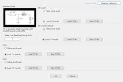
Figure 4 shows an example of the database calibration kit inputs. These calibration techniques are executed via high-performance coax, waveguide, or on-wafer.
Broadband Calibrations
The list of calibration algorithms is huge. Some popular on-wafer/free-space broadband calibration algorithms, which are based on the characteristics of transmission lines and the delta between two or more of the same type, are discussed below. These algorithms rely on idealized transmission lines, as the various lines must have the same propagation characteristics, impedance, and connector interfaces. Here’s a breakdown of each:
- Line-Reflect-Line (LRL): Sometimes referred to as TRL, this algorithm’s major advantage is that it provides the highest accuracy and has minimal standard definition. It requires very good transmission lines, though, and needs more care because it has less redundancy. It’s also band-limited.
- Multiline TRL (mTRL): This is a highly accurate method with minimal standard definition, too. One negative of mTRL is that it requires very good transmission lines. It also uses as many as 10 lines—all lines are used at each frequency in a least-square sense, with band limitations. It typically requires more lines than LRL for best performance.
Magnitude and Phase Stability
In broadband and mmWave measurements, stability often is of interest due to the possibility of long measurement sessions or longer calibrations. The preference is for a long-lasting calibration that reduces the chance of invalid measurements and overall time spent calibrating.
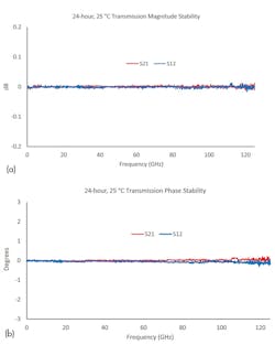
The modular broadband approach offers several advantages to help achieve these goals. For instance, it places the high-frequency couplers at the 1-mm (or 0.8-mm) connector to minimize raw-directivity degradation. Other benefits are a small integrated package to avoid thermal gradients and a tightly integrated control system. The result is good stability in reflection and transmission over time (Fig. 5).
Measurement Challenges
Measurements may be made once the VNA is calibrated. For passive components, the S-parameter measurements necessary to determine phase are straightforward. One application—materials measurements—is affected by higher frequencies when measuring phase/group delay. Therefore, it’s important to know which material category is being tested:
- Insulators (dielectrics): The energy gap between the valence and conduction band is extreme, so no free electrons are available.
- Semiconductors: The energy bandgap is smaller, so there may be some electron movement from the valence band to the conduction band.
- Conductors: The conduction and valence bands overlap, so electrons can move freely between the valence and conduction bands.
Some material measurement methods rely heavily on the change of phase imposed by the material under test. If the VNA isn’t able to measure phase with a higher degree of resolution, the measurement accuracies will degrade significantly. Hence, the VNA becomes a very important tool when making material measurements.
Oftentimes, mmWave signals are at lower power levels than traditional RF or microwave applications. The power requirements for active devices operating at a higher frequency typically are extremely low, generally −25 dBm or below. Most current VNAs can’t conduct sweeps down to a level of −50/−60 dBm very accurately to +10 dBm, so this measurement is difficult based on specification. There are exceptions, though, such as the Anritsu VectorStar VNA-based broadband mmWave system. It can go beyond −50 dBm with high accuracy thanks to the company’s NLTL technology in the mmWave modules.
Because accurate measurements on active devices demand extremely low input power, a key factor is how a VNA applies power to the input of the device. A certain level of power handling must be assured or the DUT will be damaged. Certain VNAs, such as the Anritsu VectorStar, have automatic level control (ALC) to assure proper power handling. With ALC, engineers can conduct very accurate power measurements at lower levels and gradually increase power for greater design confidence. An external power meter also can be used to perform power calibrations.
It should be noted that complete calibration standards aren’t always available at the end of the VNA fixtures. In these cases, advanced de-embedding and network extraction tools are necessary to achieve repeatable and stable measurements.
Conclusion
Phase has become an important measurement in verifying the new generation of designs that combine mmWave frequencies and small packaging. To ensure repeatable and stable measurements, proper calibration techniques must be instituted, thereby saving time and increasing design confidence.
About the Author
Navneet Kataria
Product Marketing Engineer, Anritsu Co.
Navneet Kataria is a Product Marketing Engineer at Anritsu Company. He has 10 years of experience in test and measurement, serving various technical and business roles.
