Algorithms to Antenna: Waveforms for 5G, 802.11ax, and NB-IoT

In this blog, I will describe how waveform building blocks can be employed in system modeling and simulation. To demonstrate this, I will focus on three emerging and important standards for wireless system design:
- 5G
- 11ax
- Narrowband-IoT (NB-IoT)
Each of these standards has a critical role in forming a wireless “ecosystem” to address a range of requirements from the highest bandwidth to the most energy-efficient solutions.
Having access to models of such waveforms can help system designers save time in setting up system-level modeling and simulation, especially when considering the level of configurability for each of these standards has grown substantially over previous generations. This growth is driven by the requirements to achieve higher levels of bandwidth, efficiency, and robustness.
Further down, I will illustrate this trend with a short example for each standard, starting with the 5G New Radio (NR) downlink waveform, which includes vast changes from the LTE equivalent waveform. As will be revealed, the number of parameters and configurations that can be defined to configure waveforms associated with these standards is quite large. This can be a source of confusion if a waveform model is implemented from scratch. It may also require a steep learning curve.
The added level of configurability also results in greater system-level complexity. This complexity makes it more important to simulate a design and system architecture early in a project to ensure success. It’s crucial that you start with tested and compliant waveforms. You can save project time and, more importantly, you can prevent the introduction of errors on portions of the system that aren’t critical components in your own system design.
5G NR Downlink Waveform
To illustrate the idea of a waveform building block, let’s start with a 5G New Radio (NR) downlink waveform, which is available in the 5G Toolbox. The number of parameters that can be defined is extensive, and covers everything from the synchronization signal definition, the carrier configuration, and the control resource set.
To start, the parameterization and generation of multiple bandwidth parts (BWPs) is required. A BWP is formed by a set of contiguous resources sharing waveform configurations on a given carrier. Each BWP can have different subcarrier spacings (SCS), use different cyclic prefix (CP) lengths, and span different bandwidths. In addition, different BWPs can overlap with each other.
With all of the parameters set in the carrier configuration, a waveform is generated directly.
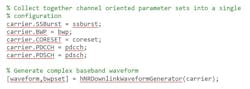
Figure 1 shows an example waveform as a function of subcarriers and symbols.
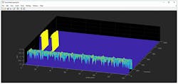
1. This is a 5G NR downlink waveform.
A structure in MATLAB with the information corresponding to an example BWP is shown below.
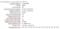
This waveform can be used to drive a simulation. See a more detailed example of implementing a 5G NR downlink carrier waveform generator using 5G Toolbox.
11ax Waveforms
IEEE 802.11ax (draft 2.0), the latest member of the Wi-Fi standard, represents an evolution of the 802.11ac standard. This standard enables more effective usage of the 2.4- and 5-GHz bands, which can increase the average throughput by a factor of 4 in high-density scenarios.
The two main enabling technologies for 802.11ax are OFDMA and multi-user (MU) MIMO. In single-user MIMO (SU-MIMO), subcarriers are employed by one user at a time. Different users utilize different timeslots to transfer data. With MU-MIMO, multiple users can exploit all subcarriers, which increases efficiency. With OFDMA, the frequency axis is divided into subsets of subcarriers and each subband or resource unit can be used by one or many users. Figure 2 shows a summary of the enabling technologies.
2. Enabling technologies for 802.11ax waveforms are illustrated here.
The IEEE P802.11ax/D2.0 standard specifies four high-efficiency (HE) packet formats:
- Single user
- Extended range single user
- Multi-user
- Trigger-based
An HE single-user (SU) packet is a full-band transmission to a single user. An extended range single-user packet has the same fields as the standard single-user format, but the powers increase for some fields. In addition, some fields are repeated to improve performance at low SNRs.
The HE multi-user (HE-MU) format can be used for an OFDMA transmission, a MU-MIMO transmission, or a combination of the two transmissions. This flexibility allows an HE-MU packet to transmit to a single user over the whole band, multiple users over different parts of the band (OFDMA), or multiple users over the same part of the band (MU-MIMO).
The HE trigger-based (TB) format allows for OFDMA or MU-MIMO transmission in the uplink. Figure 3 shows how these waveforms can be configured and generated.
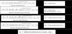
3. Here’s how 80211.ax waveforms are configured and generated.
As with the 5G waveform example, the added waveform complexity makes it more important to model the system before it’s built. With waveform models in place, you can perform waveform generation and end-to-end link-level simulation for single-user, multi-user MIMO, and OFDMA configurations of the standard.
Get a much more detailed description in the example “802.11ax Parameterization for Waveform Generation and Simulation.”
NB-IoT Waveforms
The last example I would like to share is based on a 3GPP standard for NB-IoT, which is optimized for low-data-rate machine-type communications in LTE-Advanced Pro Release 13. NB-IoT provides cost and power-efficiency improvements because it avoids the need for the complex signaling overhead required for LTE-based systems. For example, this includes reduced peak rates and support for half-duplex operation.
You can generate standard-compliant, NB-IoT uplink complex baseband waveforms representing the 180-kHz narrowband carrier suitable for test-and-measurement applications.
The NB-IoT uplink consists of the following physical-layer channels and signals:
- Narrowband demodulation reference signal (DM-RS)
- Narrowband physical uplink shared channel (NPUSCH)
- Narrowband physical random access channel (NPRACH)
Figure 4 shows the NB-IoT workflow to configure, generate, and visualize a waveform.
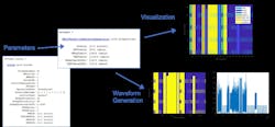
4. Generating NB-IoT waveforms involves this type of workflow.
You can learn about details of each algorithm in MATLAB. In addition, you can customize your waveforms or receiver operation. As with the other waveforms I described, you’re able to link your generated waveforms to test-and-measurement devices, RF instruments, and SDRs to perform over-the-air testing of your designs.
To learn more about the topics covered in this blog, see the links below or email me at [email protected].
- What Is 5G Toolbox? (video): Learn to simulate, analyze, and test the physical layer of 5G communications systems using 5G Toolbox.
- 11ax Standard in WLAN Toolbox (example): Learn how to parameterize and generate different IEEE 802.11ax high-efficiency (HE) format packets.
- NB-IoT Uplink Waveform Generation (example): Learn how to generate LTE-Advanced Pro Release 13 NB-IoT uplink waveforms consisting of the NPUSCH and the associated demodulation reference signals for test-and-measurement applications.
See additional 5G, radar, and EW resources, including those referenced in previous blog posts.

About the Author
Rick Gentile
Product Manager, Phased Array System Toolbox and Signal Processing Toolbox
Rick Gentile is the product manager for Phased Array System Toolbox and Signal Processing Toolbox at MathWorks. Prior to joining MathWorks, Rick was a radar systems engineer at MITRE and MIT Lincoln Laboratory, where he worked on the development of several large radar systems. Rick also was a DSP applications engineer at Analog Devices, where he led embedded processor and system level architecture definitions for high performance signal processing systems used in a wide range of applications.
He received a BS in electrical and computer engineering from the University of Massachusetts, Amherst, and an MS in electrical and computer engineering from Northeastern University, where his focus areas of study included microwave engineering, communications, and signal processing.
