Algorithms to Antennas: Optimization Techniques for Phased-Array Synthesis
This blog is part of the Algorithms to Antenna Series
What you'll learn:
- How to apply optimization techniques to phased-array designs.
- What is quadratic programming?
- Using optimization solvers in the design process.
In a previous blog post, we discussed examples that show how you can synthesize a phased-array design to achieve a desired pattern. In this post, we expand on a topic that applies to radar and wireless system applications that use phased-array front ends.
This type of optimization workflow can save lots of time when you design a large phased-array system because multiple design parameters are in play, including the individual element location and the weights applied to each element. These optimization techniques can be used when you’re working on the physical design of the array at the electromagnetic solver level and when working at the system level.
Here we focus on the system-level application, but we have included a link to more resources at the end of this post for electromagnetic solver applications. These will also be a topic for a future post.
Compared with a single antenna element, a major benefit of a phased array is that you can form a beam (or multiple beams) to strengthen desired signals and reduce the impact of interference signals. In general, an N-element phased array provides N degrees of freedom when synthesizing a pattern. This means that we can adjust N weights, one for each element, to control the shape of the beam to satisfy some predefined constraints.
As we noted in our previous blog, pattern synthesis can be achieved using a variety of techniques, including nulling, windowing, and thinning. Applying optimization techniques helps remove the “trial and error” process in pattern synthesis.
Many popular beamforming techniques can be expressed as an optimization problem. For example, the minimum variance distortionless response (MVDR) beamformer is used to minimize the total noise output while preserving the signal from a given direction. We have blogged on these types of beamformers previously, but mathematically, the MVDR beamforming weights can be found by solving an optimization problem.
We’ve left out the math here, but an N-element array is able to handle N−1 constraints. The MVDR beamformer can be extended to include more constraints, which results in a linearly constrained minimum variance (LCMV) beamformer. The extra constraints in an LCMV beamformer are often used to null out interferences from given directions.
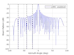
These techniques apply to any array geometry, but let’s consider a 32-element uniform linear array with half-wavelength spacing between elements. We can perform array synthesis using the LCMV approach. Our signal of interest is at 0 degrees azimuth and the interference sources are at −70, −40, and −20 degrees azimuth. The noise power is assumed to be at 40 dB below signal. Figure 1 shows the results of our pattern. This beamformer does a nice job of eliminating our noise sources in the directions shown in the plot with the vertical dashed lines.
One thing that MVDR and LCMV algorithms have in common is that they only address equality constraints. However, another common requirement for pattern synthesis is to ensure the array response is below a certain threshold for a set of given angles. For example, we can add the following requirements to our desired pattern:
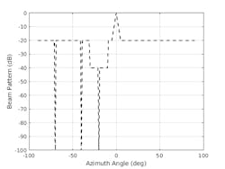
1. The sidelobe should be below −40 dB between −30 and −10 degrees in azimuth.
2. Everywhere outside of the mainlobe, the sidelobe should be below −20 dB.
Figure 2 illustrates the desired pattern requirements of the system we will attempt to achieve.
MVDR and LCMV algorithms can no longer be used to solve this type of problem, so we would like to introduce another technique involving an optimization solver.
Optimization solvers are used to minimize an objective function for a given set of constraints. Some optimization solvers are more efficient than others based on the objective function and constraints in place. Therefore, it’s important to select the proper optimization solver for your application. In our case, because the objective function is in the form of minimizing the power, it’s natural to consider it as a quadratic-programming (QP) problem. For example, you can use the quadprog function from Optimization Toolbox.
Although QP solvers seem to be a good fit to our pattern synthesis problem, it’s not straightforward to translate the array synthesis problem to a QP formulation. This is because the solvers normally deal with real numbers while the array pattern computation involves complex numbers. We need to first convert complex operations to real operations to form both real and imaginary parts of the objective function and constraints, and then set up the quadratic programming and use the solver.
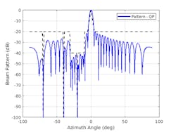
Figure 3 shows the resulting pattern using the synthesized weights. Note the overlaid dashed lines, which represent our desired requirements. Nulls exist at −70, −40, and −20 degrees azimuth, and the new sidelobe levels have been achieved.
The quadratic programming can get the job done. However, to convert the complex constraints to real constraints, we’re forced to consider real and imaginary parts separately while in theory, we only need to ensure that the norm of the two satisfy the inequality. Therefore, in QP formulation, we put tighter constraints on both real and imaginary parts of the beam pattern.
Another kind of optimization solver, called second-order cone programming (SOCP), has constraints defined in the form of a norm. This provides another viable option for our problem. Furthermore, because constraints in our pattern synthesis problem match the SOCP formulation more naturally, we expect the result from SOCP might be better than those achieved by QP.
However, even though the objective function of a SOCP problem is a linear function rather than a norm, it’s possible to transform the original objective function with norm to an extra second-order cone constraint. The SOCP then can be used to solve our minimum variance pattern synthesis problem.
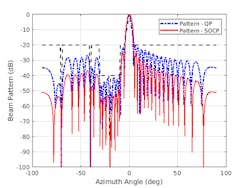
Figure 4 shows the pattern achieved using the coneprog function from Optimization Toolbox. Comparing this result with the pattern derived from QP, we can see that the SOCP solver achieves a lower sidelobe level.
You can use Phased Array System Toolbox, Antenna Toolbox, and Optimization Toolbox to design the arrays in your system. To learn more about the topics covered in this blog and explore your own designs, see the examples below or email me at [email protected]:
- Array Synthesis Code (example code): See example code for optimization techniques to synthesize the arrays.
- Array Pattern Synthesis (example): Learn to design a phased array to match a desired beam pattern to a specification.
- Antenna and Array Optimization (documentation): Learn to use the Antenna Designer and Antenna Array Designer apps to optimize antenna design, based on electromagnetic solvers, for various analysis parameters, such as impedance, gain, directivity, current, and charge, for given constraints.
See additional 5G, radar, and EW resources, including those referenced in previous blog posts.
About the Author
Rick Gentile
Product Manager, Phased Array System Toolbox and Signal Processing Toolbox
Rick Gentile is the product manager for Phased Array System Toolbox and Signal Processing Toolbox at MathWorks. Prior to joining MathWorks, Rick was a radar systems engineer at MITRE and MIT Lincoln Laboratory, where he worked on the development of several large radar systems. Rick also was a DSP applications engineer at Analog Devices, where he led embedded processor and system level architecture definitions for high performance signal processing systems used in a wide range of applications.
He received a BS in electrical and computer engineering from the University of Massachusetts, Amherst, and an MS in electrical and computer engineering from Northeastern University, where his focus areas of study included microwave engineering, communications, and signal processing.
