Radar Systems for Autonomous Driving—at L2/L2+ and Beyond

This article appeared in Electronic Design and has been published here with permission.
What you’ll learn:
- How self-driving cars are adding new capabilities as they move from Layer 2 (L2) to L2+ and beyond.
- How automotive radar systems are designed, and what this means for processors and other components.
- Why vector DSPs provide a flexible, scalable answer to the high-performance demands of automotive radar processing.
It's a technology that feels like it's been nearly there for years, but we're still waiting for full autonomy in cars, and it's much further out than we originally thought.
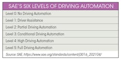
Industry body SAE defines six levels of driving automation (see table), from no automation up to full self-driving at level 5. As vehicles become more automated and reach higher levels, they’re more tightly regulated and require more sophisticated systems to provide a safe, reliable solution.
The automotive industry has been looking to a move to level 3 (L3), but right now this seems unrealistic. Instead, there's a very active push from SAE level 2, conventional advanced driver-assistance systems (ADAS), to something now being called L2+. This is a chance for OEMs and Tier 1s to monetize their investments in full autonomy systems, in car models that will come to production as early as 2023.
L2+ is a little short of L3, in that redundancy continues to depend on the human driver. Thus, the number of additional sensors compared with L2 systems is limited, but it would still enable supporting advanced new safety features in affordable ADAS systems. In L2+, radar sensors are expected to be added to the basic suite of camera sensors. Radar is affordably priced and provides significant complementary benefits to the known weaknesses of camera sensors in extreme lighting and weather conditions.
L2+ offer significant advances over current L2 ADAS, in urban driving, highway automation, lane changes, and merges. And it can arrive much sooner than L3, without the need for fundamental changes to regulation, infrastructure, and social acceptance.
Time is Now for L2+
Autonomous driving compute platforms will eventually migrate to central computing architectures doing the heavy lifting, with sensor fusion from myriad 360-degree coverage sensors and sensor types. In the shorter term, L2+ systems will come in various form factors, some anticipating future central computing platforms doing early fusion of various sensors.
Mostly, they will still use discrete smart sensors with most of the sensor processing load handled on the edge, and specifically for radars that will complement basic camera-based systems. Therefore, it’s expected that the majority of radar devices in the upcoming years would still execute most of the radar chain processing within the radar device itself, and they will require strong compute platforms.
Market forecasts expect mass production ramp-up of L2+ ADAS systems starting from 2023, with initial deployment of higher autonomy levels—L3 and above—starting no earlier than 2026-2027. As for radar, HD radars will mostly be used for L3 and higher autonomy levels, at least until their price point drops enough to be integrated in L2+ ADAS systems, which isn’t expected before 2028.
Thus, there’s a significant market window of at least six years when standard radar devices will still dominate the market. And they will play a vital role in L2+ ADAS systems, with more radar nodes per vehicle to implement more ADAS features and 360-degree coverage (Fig. 1).

How Does It Work?
The basic principle of radar is interferometry. Signals are transmitted from an array of transmit antennas and received through an array of receive antennas. The range, velocity, and direction of objects and obstacles can be estimated from the relative phases of the received signals, which have bounced back off them.
As such, radar delivers direct perception-related inputs, using highly deterministic processing techniques to extract depth-related features. This is contrary to camera sensors, which require complex (though well-known and tried) computer-vision (CV) and artificial-intelligence (AI) processing to achieve the same kind of outputs.
The number of effective "virtual" radar channels is the product of the number of transmit (TX) and receive (RX) antennas. For example, a typical radar device used in today's L2/L2+ vehicles includes 3TX and 4RX antennas, for an overall total of 12 virtual channels. This is enough to support basic L2/L2+ features like automatic emergency braking (AEB) and adaptive cruise control (ACC).
The radar devices we will see in future L2+ and above systems will include 12Tx16R (for an overall 192 channels), and even as much as 48Tx48R (for a staggering 2304 channels). These larger configurations are referred to as HD imaging radar, or 4D radar (being able to extract the four parameters of range, velocity, azimuth, and elevation).
The main benefit of more channels is to increase the radar accuracy, and specifically the angular resolution in both azimuth and elevation. HD radar can achieve angular resolution of below 1 degree for a long-range object, which can be as far as 200 meters away. Azimuth resolution enables object detection (such as pedestrians), while elevation resolution allows a system to distinguish between vehicles and overhanging street furniture. Increased resolution allows us to reduce false positives resulting from wide side-lobes, which is a known issue in common small-scale radar devices.
Radar Chipsets—Sensors and Signal Processors
Radar chipsets are usually comprised of two main components: the sensor, or radar transceiver, handling the RF signals from the millimeter-wave (mmWave) antennas down to the baseband signal, and the radar microcontroller (MCU) handling the digital radar signal processing.
The radar transceiver and MCU are typically two different chips, each manufactured in its optimal and cost-effective process node. While the complexity of the radar transceiver is linearly proportional to the number of antennas, or physical RF chains, the complexity of the signal processing performed in the radar MCU is related to the number of virtual channels. Hence, it’s quadratic with the number of antennas (and rises much faster as the system becomes more complex).
Figure 2 shows a typical radar processing chain. The RF front end is implemented in the radar transceiver. After analog-to-digital conversion, the signal is processed in the radar MCU.
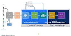
The radar processing chain is typically divided into two main parts:
- The radar front-end processing, which outputs the radar point cloud.
- The radar post-processing, which is handling object classification and tracking.
These two disparate workloads require different kinds of processing elements and techniques. Depending on the MCU architecture, both front-end and post-processing can be integrated into a single MCU, or else the latter parts of the chain can be processed in a central electronic control unit (ECU).
After pre-processing by a time-domain digital front end (involving mainly filtering), the signal is processed by the radar front-end module. Processing is typical of common frequency-modulated continuous-wave (FMCW) types of radars.
The front-end processing involves first the range-Doppler fast Fourier transform (FFT) and constitution of the radar data cube (accumulating data from multiple antennas and radar pulses), followed by first target detections using constant false alarm rate (CFAR) algorithm variants, and then degree-of-arrival/angle-of-arrival (DoA/AoA) angle estimation. The output of the radar front-end processing is called the radar point cloud, and for each detected point it includes the 3D or 4D range/Doppler/angle information.
For HD radar, the radar front-end processing can be extremely computationally heavy, and will typically be implemented in optimized hardware. However, small-scale radar front ends (for example, with 12 to 16 virtual channels) lend themselves to a more software-oriented implementation and a more flexible partitioning between hardware and software.
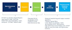
The processing engine needs to cope with various types of computations. FFT and CFAR can be efficiently implemented using fixed-point arithmetic, while angle-estimation algorithms typically make extensive use of matrix decomposition and require floating-point arithmetic.
After the point cloud, the radar post-processing involves target recognition, segmenting, tracking, and classification. This uses heavy matrix operations in high-accuracy floating-point arithmetic, implementing algorithms such as Kalman filtering, involving operations like matrix inversion, Cholesky decomposition, and nonlinear operations. This type of processing is typically implanted on DSP cores, to allow for maximum flexibility and enable different vendors to differentiate and innovate.
Finally, target classification and sensor fusion uses AI inferencing techniques and requires heavy processing of neural networks.
Pulling It All Together—a DSP-Based Radar Processing Platform
As discussed, modern radar processing involves significant computational and implementation challenges to build an end-to-end chain. As this is a still-evolving technology, with consideration of future autonomy levels, designers need both the flexibility of software and a scalable high-performance computing platform. This lends itself to platforms based on powerful vector DSPs.
We’ve seen that the scale and dimensioning of modern automotive radar devices can vary significantly, between common 12-channel devices and a high-end imaging radar with thousands of channels. In addition, each device must perform a wide variety of algorithms and support different arithmetic processing engines to cope with different workloads (Fig. 3).
An example of a scalable vector architecture suitable for this application is CEVA’s SensPro-Radar. Building on CEVA’s second-generation SensPro2 IP family, it can handle the wide variety of required workloads for radar chain signal processing. This means that developers can use the same platform, and same development tools, for all parts of their solution, and across different generations.
For radar front-end processing, there is the optional SensPro-Radar ISA, which adds special instructions for accelerating the range/Doppler FFT and complex arithmetic operations. The SensPro-Radar ISA can efficiently map a significant part of the radar front-end to the DSP core, which improves implementation flexibility, and reduces time-to-market.
A typical radar chain implementation must process huge amounts of data, depending on the number of virtual channels. The SensPro architecture uses CEVA’s advanced memory subsystem that provides easy access to the radar data cube with “tiles” across different dimensions.
To complement the computing platform, CEVA offers software libraries, including Eigen Linear Algebra. CEVA’s Radar SDK for SensPro makes extensive use of the dedicated Radar ISA and gives software developers a complete radar chain reference implementation.
Conclusion
As cars add new autonomous-driving capabilities, and specifically as they move from L2 to L2+ and beyond, there’s a growing requirement for them to add radar to their suite of sensors. This does place new demands on the on-vehicle processing architecture, particularly as more channels and HD radar massively increase the complexity of the data captured and analyzed.
Having a single platform that can effectively process all radar-related workloads, both front-end and post-processing, allows the radar architect to freely choose the optimal hardware/software partitioning, while still reserving enough software flexibility for future-proofing the solution. Furthermore, the balance between the different kinds of workloads can be changed dynamically, post-silicon production. This kind of architecture is ideally suited for over-the-air (OTA) updates, which will be important in future autonomous platforms and autonomy-as-a-service.
About the Author
Nir Shapira
Director for Strategic Technologies, CEVA Inc.
Nir Shapira is a Business Development Director in CEVA Mobile Broadband BU. Nir has been in the communications industry for more than 25 years. Prior to joining CEVA, Nir was the CTO at Wiliot, doing battery-less Bluetooth, and the CTO of Celeno Communications from its inception, doing carrier-grade Wi-Fi. Nir has made significant contributions to standardizations, notably 802.11, and has dozens of patents in the field of communications. Nir holds a B.Sc. (summa cum laude) from the Technion, Israel.
