Modeling the Way to a Better Anechoic Chamber
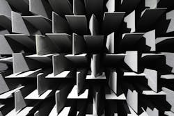
Anechoic chambers are useful test environments for many RF/microwave systems designs, including radar, for their absence of ambient radio waves. They are constructed with different dimensions and using radar-absorbing materials (RAMs) to reduce the levels of reflected RF/microwave energy within the chamber. One challenge in constructing such chambers is in optimizing performance with different RAMs and room sizes and configurations. For that purpose, researchers from various institutions in China applied geometric optics (GO) to the design and optimization of anechoic chambers in a number of different configurations. They validated their simulation solutions by comparison with several actual semi-anechoic chambers to compared simulations with measurements, with fairly close agreement.
One goal established by the researchers was to develop an effective system-level computer-aided-design tool to describe the characteristics of the RAM without losing accuracy or efficiency. The far-field pattern of the test antenna is used as an excitation source rather than a three-dimensional (3D) model of the antenna as typical in full-wave simulations. In GO analysis, the electric (E) field is assumed to propagate in an anechoic chamber much like light, and the researchers developed forward and inverse algorithms to model electromagnetic (EM) propagation in the anechoic chamber as if it were emanating from an optical source. Algorithms were developed with the aid of MATLAB mathematical simulation software from The MathWorks and the chamber was modeled by means of ASCII stereo lithography (STL) file.
Modeling involved determining the forward propagation paths in all directions from an antenna source using the forward algorithm, and then back tracking the reverse paths by means of the inverse algorithm. To validate the models, several semi-anechoic chambers were used for measurements, including a compact chamber measuring 22.0 × 13.5 × 8.0 m. This chamber contained half-wave dipole antennas for receive and transmit functions, both at a height of 2 m. Different types of RAM were used and each type of RAM was characterized and the complex reflection coefficients for different angles were determined. The work led to a systematic solution for the analysis and design of, hopefully, a better anechoic chamber.
See “Building a Better Anechoic Chamber: A Geometric Optics-Based Systematic Solution, Simulated and Verified,” IEEE Antennas & Propagation Magazine, Vol. 58, No. 2 April 2016, p. 94.
Looking for parts? Go to SourceESB.
This file type includes high resolution graphics and schematics when applicable.
About the Author
Jack Browne
Technical Contributor
Jack Browne, Technical Contributor, has worked in technical publishing for over 30 years. He managed the content and production of three technical journals while at the American Institute of Physics, including Medical Physics and the Journal of Vacuum Science & Technology. He has been a Publisher and Editor for Penton Media, started the firm’s Wireless Symposium & Exhibition trade show in 1993, and currently serves as Technical Contributor for that company's Microwaves & RF magazine. Browne, who holds a BS in Mathematics from City College of New York and BA degrees in English and Philosophy from Fordham University, is a member of the IEEE.
