Software-Defined-Radar Evaluation Kits Reach a Wide Range of Applications
This file type includes high resolution graphics and schematics when applicable.
A software-defined-radar (SDR) system can utilize software protocols to implement transmitting and receiving functionality. These systems are hitting the market thanks to companies like Ancortek. The Virginia-based company, founded in 2013, offers short-range, lightweight, low-power SDR evaluation/development kits to support applications like industry automation, medical diagnosis, and public safety and security.
These SDR systems offer a number of advantages, such as their compact size and flexibility. Operating modes, waveforms, bandwidths, and processing functions can be changed without requiring hardware modifications. Expandable waveform bandwidth, real-time processing, programmability, and re-configurability are additional benefits of these SDR systems.
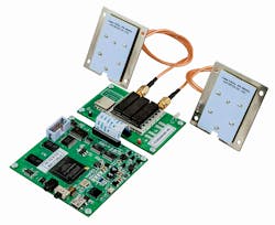
Each SDR evaluation kit includes an RF module, an FPGA-based processor module, and a graphical-user-interface (GUI) (Fig. 1). The required cables, antennas, and power adapter are also included. Five different RF modules are currently offered: the SDR-RF 240B, SDR-RF 580B, SDR-RF 620B, SDR-RF 980B, and SDR-RF 2500B. These modules have operating-center frequencies of 2.45, 5.80, 6.20, 9.80, and 25.0 GHz, respectively. Ancortek offers five separate SDR kits—one for each RF module. The part numbers for the kits are SDR-KIT 240B, SDR-KIT 580B, SDR-KIT 620B, SDR-KIT 980B, and SDR-KIT 2500B. The SDR-PM 402 processor module is compatible with all RF modules, and is included in every kit.
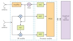
An SDR system block diagram illustrates the RF module, processor module, and GUI (Fig. 2). In addition to the FPGA, the processor module consists of a 12-bit digital-to-analog converter (DAC) and two 12-bit analog-to-digital converters (ADCs). Because the SDR kits are intended primarily for short-range applications, a frequency-modulated-continuous-waveform (FMCW) radar-system architecture is utilized.
This architecture enables short range and velocity to be measured accurately and simultaneously. A direct-conversion homodyne receiver mixes the received signal with the transmitted FMCW signal, resulting in a signal with very low frequency—in the hundreds of kilohertz. As a result, the ADC sampling rate requirements can be eased considerably. Specifically, the DAC and ADCs operate at sampling rates of 40 Msamples/s. Continuous-wave (CW) and frequency-shift-keying (FSK) waveforms are also available with the same system architecture.

The GUI includes a control panel, a graphic panel, and a video display. Users can select various options for operation modes, signal waveforms, operating parameters, filtering types, display modes/parameters, and data recording for exporting. The graphic panel displays real-time graphical representations of signals in the time domain, frequency domain, and combined time and frequency domain.
Users can record raw data streams, which can be saved as binary data files for post-processing. For academic research purposes, a MATLAB version of the GUI and its source codes is also available. This allows users to save raw data as a MAT file or to modify MATLAB source code to implement user-developed signal processing and analysis tools.
In regard to RF module performance, the SDR-RF 2500B, which operates from 24 to 26 GHz, achieves typical transmitter output power of +19 dBm. Its receiver attains 28 dB of gain along with a noise figure of 6.4 dB. The SDR-RF 2500B boasts typical phase noise of -100 dBc/Hz at 1-MHz offset. Its tuning voltage ranges from 0 to +5 V with a tuning sensitivity of 1.5 GHz/V. The SDR-RF 2500B typically draws 800 mA current from a supply voltage of +5 VDC. It is built for an operating temperature range of -40°C to +85°C.
This file type includes high resolution graphics and schematics when applicable.
