Designers working with electromagnetic (EM) energy are constantly faced with the threat of leaksthat stray EM energy could make its way into the parts of a circuit or system where it can do more harm than good. When this happens, the EM energy takes on the form of electromagnetic interference (EMI). It can disrupt the performance not only of the circuit or system it originates from, but of circuits and systems nearby. Fortunately, there are numerous ways to detect and fix EMI problems. The process of designing or modifying electronic devices to operate without interfering with each other, when in close proximity, is known as achieving electromagnetic compatibility (EMC).
EMI can be difficult to spot because it comes in many forms, such as naturally occurring (solar radiation, lightning), manmade, continuous, impulse, narrowband, broadband, radiated, and conducted energy. Because it can occur only at certain frequencies, EMI can also be difficult to measure and model, and typically requires considering not only fundamental frequencies in a circuit or system, but also harmonic frequencies and spurious signal content.
At the circuit level, any long signal trace on a printed circuit board (PCB) can double as an antenna, or radiating source of EM energy. Signal interconnections can also be guilty of unwanted EM radiation. EMI can have electric (E) field and/or magnetic (H) field characteristics. For example, in circuits with high voltages but low currents, the field strength of the E field is much higher than that of the H field, and the E field is said to dominate. In circuits with low voltages and high currents, the reverse is true, and the H field dominates. The E field intensity is measured in V/m while the H field intensity is measured in A/m. The EM wave impedance, Zw, which is the ratio of the E field intensity to the H field intensity, is measured in Ω.
At the system level, tracking and controlling EMI can be even trickier, since multiple EMI may exist (such as local oscillators within a receiver), and they may be positioned within a close distance to components that can be impacted by the radiated emissions (such as frequency mixers or analog-to-digital converters ). When all of these components are packed within a metal enclosure, the enclosure can provide a means of achieving an effect groundto reduce EMIbut can also serve as a means of reflecting and re-radiating unwanted EMI.
In addition to making an electronic design perform properly, EMI must come into compliance with standards set by different organizations around the world, including the US Federal Communications Commission (FCC) and International Electrotechnical Commission (IEC). The US military standards are even stricter, and are outlined in such documents as MIL-STD-461D, "Requirements for the Control of Electromagnetic Interference and Emissions and Susceptibility," and MIL-STD-462D, "Measurement of Electromagnetic Interference Characteristics."
Analysis of circuits and systems for EMI usually involves a broadband spectrum analyzer or EMI test receiver. Proponents of both test instruments will debate the merits of each for EMI measurements, and each has its advantages and disadvantages. the debate is detailed in a white paper (in PDF form) from Rohde & Schwarz, "RMI Measurements, Test Receiver vs. Spectrum Analyzer."
Achieving EMC requires full control of the EM environment, and this usually involves placing a circuit or system under test in an anechoic chamber to eliminate outside RM sources. once within an RM-sealed environment, not only is it possible to detect radiated emissions from the circuit under test, but it is also possible to introduce high-level EM sources to evaluate the susceptibility of the circuit or system to EM. Several companies, such as Amplifier Research (AR) and Instruments For Industry, provide not only amps, but complete EMC test systems.
In terms of modeling designs for EMI and EMC, the number of EM simulators is many, based on a variety of different analysis techniques. Sorting through the number of software packages, which include stand-alone programs as well as modules within larger system-level simulators, can be daunting. For that reason, the IEEE offers a 21-page report, "An EMC Engineer's Guide to Electromagnetic Modeling Software," which summarizes the many different EM programs currently available, with a generic review of analysis types and modeling features. The report is available from the IEEE for free at http://www.ieee.ca/diglib/library/9712hubing/hubing.pdf.
Any design can be susceptible to EMI, no matter how careful the planning. Because of the need to control EMI, an industry has grown up around the development of shielding materialssuch as gaskets, conductive adhesives, and even conductive paintswhich can be added to the enclosure of an electronic product to achieve EMC. Just how well an EM shield works is measured by its shielding effectiveness (SE).
An EM shield is essentially any barrier placed between an EM emitter and a susceptor, and it is designed to reduce the field strength of the emitter. The losses in EM emitter field strength are a function of the barrier's electrical and physical characteristics, such as its permeability, conductivity, and thickness; the frequency of the EMI; and the distance from the EMI source to the barrier/shield. The total SE of the shield is the sum of the reflection, absorption, and re-reflection losses.
As an example, CHO-SEAL 6502 and 6503 from Chomerics are nickel-plated aluminum (Ni/Al)- filled silicone and fluorosilicone elastomers that are suitable for hostile environments. The materials are capable of SE performance greater than 100 dB.
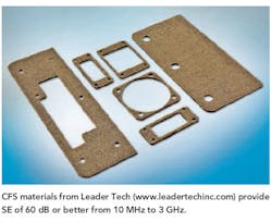
New CFS conductive-foam shielding materials from Leader Tech can be produced in almost any form and configuration to form die-cut gaskets for a wide range of enclosures in commercial and military applications. Offering SE of 60 dB or better from 10 MHz to 3 GHz, the CFS materials (see figure) consist of a low-resistance polyester fabric surface and a resilient nickel-copper polyurethane foam center. The dBseal gaskets from Dow Corning are also designed for easy application and high levels of EMI shielding.
Fortunately, companies offering solutions for EMI and EMC also offer ample advice, such as the four-page "EMI/RFI Shielding Management Tips and FAQs" guide from AI Technology or the four-page "EMI Shielding Design Guide" from Enthone. One of the better free guides is the 22-page "EMI Shielding Design Guide" from Tecknit, now part of Parker Chomerics.
About the Author
Jack Browne
Technical Contributor
Jack Browne, Technical Contributor, has worked in technical publishing for over 30 years. He managed the content and production of three technical journals while at the American Institute of Physics, including Medical Physics and the Journal of Vacuum Science & Technology. He has been a Publisher and Editor for Penton Media, started the firm’s Wireless Symposium & Exhibition trade show in 1993, and currently serves as Technical Contributor for that company's Microwaves & RF magazine. Browne, who holds a BS in Mathematics from City College of New York and BA degrees in English and Philosophy from Fordham University, is a member of the IEEE.
