When to Combine True Time Delays and Phase Shifters in a Hybrid Beamforming Approach
Electronically scanned arrays (ESAs) utilize phase shifters (PSs), true time delays (TTDs), or a mix of both to point the summed beam toward the desired direction within an array’s steering angle limits. Adjustable attenuators used for tapering also can be considered as beamforming elements.
This article discusses where and how a tiered approach between TTDs and PSs in the same ESA can be helpful to mitigate some phased-array design challenges.
Leverage Fundamental Formulas to Explore Possible Scenarios
Instantaneous bandwidth (IBW) can be defined as the frequency band where no tuning is required to stay within the target performance criterion set by the system requirements.
TTDs exhibit constant phase slope over frequency; therefore, ESAs implemented with TTDs instead of PSs don’t have beam squint effect. As a result, TTD-based ESAs are more convenient for high-IBW applications.
PSs exhibit constant phase over their operating frequency range. Hence, a particular phase-shifter setting throughout the system results in different beamsteering angles for different frequencies. Consequently, PS-based arrays tend to have narrower IBW compared to TTD-based arrays.
This phenomenon is called beam squint and it can be calculated using Equation 1, where Δθ is peak squint angle, θ0 is maximum beam angle, f0 is carrier frequency, and f is instantaneous signal frequency:
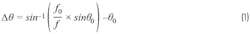
Using Equation 1, we can calculate that Δθ at worst case, which is at the low frequency edge (carrier at 3 GHz and instantaneous signal at 2.9 GHz), is around 1.15 degrees for a ±30-deg. beamsteering-angle system for a signal at 3 GHz with an IBW of 100 MHz. Changing beamsteering angle to ±60 deg. and IBW to 200 MHz results in a worst-case beam squint of around 8.11 degrees.
It’s evident that TTDs can be a better choice even in radar applications. Arguably, phase-shifter dominance in ESAs is explained by the fact that PSs have had wider market availability due to their design simplicity and cost advantage over TTDs.
If we had a TTD that meets the system requirements, how might it be reasonable to use PSs in the same signal chain? To investigate, we’ll examine a 32 × 32 square ESA with d = λ/2 lattice spacing between antenna elements desired to operate between 8 and 12 GHz with a ±60-deg. scanning angle. EIRP criteria is assumed to be met for all scenarios.
In this example, the system beamwidth in both azimuth and elevation would be ≅3.17 deg. at boresight (θ = 0 degrees) and ≅6.35 deg. at the maximum scan angle (θ = 60 deg.) by the half-power beamwidth approximation formula for a uniform linear array given in Equation 2:

where N is the number of elements on one axis and θB is the beamwidth in degrees on the same axis.
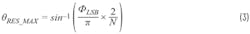
The maximum beam-angle resolution (θRES_MAX) of this array would be approximately ≅0.056 deg. in one dimension when using 6-bit, 5.6-deg.-LSB PSs behind every antenna element:
Approximately 1.3-ps LSB TTDs would be required to replace 5.6-deg.-LSB PSs to have a 0.056-deg. beam angular resolution at 12 GHz (from Equation 4, which is used for conversion between time and phase shift):

The beamwidth value is considerably greater than the beam angular resolution even at very small scan angle. Placing PSs on the same line with TTDs to compensate for beam angular resolution would introduce additional beam squint and degrade beam angular resolution.
In practice, the reason to have finer TTD resolution is to maintain lower quantization sidelobe levels (QSLL) rather than having finer beam angular resolution. As the frequency goes higher, designing a TTD with the required time resolution to meet the target QSLL criteria gets relatively more difficult than designing a PS with a required phase resolution. Therefore, PSs can work with TTDs to achieve the target QSLL while still having an acceptable level of beam squint.
Cross-Polarization Systems
Another reason to implement PSs and TTDs in the same ESA could be to mitigate beam squint while designing a system with cross-polarization capability. Cross polarization is generated by setting a 90-deg. phase shift in between the V and H feeds of antenna elements. Ensuring as close to a 90-deg. difference as possible between feeds over the desired cross-polarization bandwidth is essential to having good cross-polarization isolation for healthy operation.
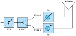
Because they offer a constant phase over frequency, PS-based ESAs have a wideband cross-polarization capability (Fig. 1). TTD-based ESAs, on the other hand, can have 90 degrees between feeds only at a single frequency (Fig. 2).
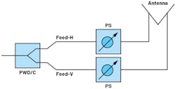
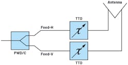
One may use the architecture in Figure 3 to apply cross polarization while mitigating beam squint.
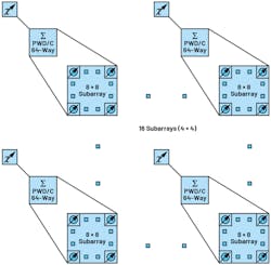
TTD coverage is set by the maximum delay ΔtMAX between the most distant elements of the whole array at the lowest frequency of operation. Using Equation 5, this is around 2.45 ns for the example array in Figure 4.

There are a couple of things to consider when using TTDs behind every antenna element instead of PSs if cross polarization isn’t required. This coverage means a significantly high loss and could be challenging to implement given the antenna spacing. Having the resolution of a 6-bit PS with the given coverage would bring some design challenges, along with many delay stages to be placed into TTDs.
If the resolution is preserved and the coverage is reduced to mitigate these drawbacks, then one would have to wrap back through zero when exceeding the coverage (by calculating the phase equivalent using Equation 4). However, ironically, the beam-squint feature would be lost.
This quick analysis shows that PSs at every antenna element followed by TTDs at the common legs of the subarrays can be useful even when cross polarization isn’t required. The TTDs in Figure 4 would again need to have the same coverage. This time, though, the resolution requirement is relaxed compared to the scenario of a TTD at every antenna element, because they’re now used to align relatively larger time delays between subarrays.
Breaking down a phased array into subarray partitions lowers the cost and complexity of a system at the expense of a higher scan loss and lower beamsteering resolution. By having wider beamwidth, subarrays are more tolerant to beam-squint effects as they have wider beamwidth. It’s apparent that beam squint and beamwidth targets are important metrics with consideration to the subarray size.
Conclusion
True time delays behind every antenna element are required for broadband, squint-free operation; and phase shifters behind every V and H feed of each antenna element are required for broadband cross-polarization operation.
If you don’t need cross polarization but are seeking fully squint-free operation, go with a TTD-based design. As the frequency increases, adding PSs could help meet the QSLL target with the tradeoff of compromised squint-free operation.
If cross polarization is required, then each polarization feed of the antenna should be followed by separate but identical PSs with a tight 90-deg. difference above the operational bandwidth. Adding TTDs on the common leg of PSs could help to mitigate the beam squint.
Whether cross polarization is required or not, a subarray architecture with PSs behind antenna elements followed by TTDs at the common legs of subarrays can be a cost-effective solution. Note that TTD functionality may be implemented in the digital domain—an all-digital design can eliminate both TTDs and PSs at the expense of a higher system cost.
Before diving into the countless challenges of ESA design, understanding the differences in using either TTDs or PSs versus using them in tandem is an essential part of planning a system-level beamforming architecture that meets the system requirements with better SWaP-C.
Read more articles in the TechXchange: Antenna Design
References
Delos, Peter, Bob Broughton, and Jon Kraft. “Phased Array Antenna Patterns—Part 1: Linear Array Beam Characteristics and Array Factor.” Analog Dialogue, Vol. 54, No. 2, May 2020.
Delos, Peter, Bob Broughton, and Jon Kraft, “Phased Array Antenna Patterns—Part 2: Grating Lobes and Beam Squint.” Analog Dialogue, Vol. 54, No. 2, June 2020.
Delos, Peter, Bob Broughton, and Jon Kraft, “Phased Array Antenna Patterns—Part 3: Sidelobes and Tapering.” Analog Dialogue, Vol. 54, No. 3, July 2020.
Stimson, George W., Hugh D. Griffiths, Chris J. Baker, and Dave Adamy. Introduction to Airborne Radar. Third Edition. SciTech Publishing, 2014.
About the Author
Bilgin Kiziltas
Field Applications Engineer, Analog Devices Inc.
Bilgin Kiziltas joined Analog Devices as a field applications engineer in 2019. He received his B.S. degree in electronics engineering from Istanbul Technical University in 2010 and his M.S. degree in RF, microwave, radar, and antennas from the electrics and electronics engineering department of Middle East Technical University in 2013. Prior to joining ADI, he worked as an RF design engineer for nine years in the phased-array department at Aselsan Radar and in the Electronic Warfare Business Sector.
