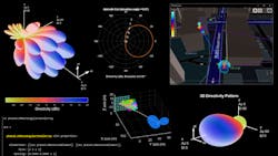
Algorithms to Antennas: Modeling 5G Antenna Elements and Arrays
This blog is part of the Algorithms to Antenna Series
What you'll learn:
- Overview on specifications related to antenna-array configurations from ITU-R and 3GPP.
- What is the the phased.NRRectangularPanelArray model component?
- Defining array elements for larger analysis/simulation functions.
In previous blogs, we have put the spotlight on a range of specific topics relating to antenna-array design for 5G systems. They include:
- 5G NR Beam Sweeping and Beam Refinement
- Designing an Antenna Array
- Understanding Subarray Tradeoffs in Large Antenna Arrays
- Modeling Mutual Coupling in Large Antenna Arrays
This edition connects these topics to published specifications related to antenna-array configurations. First, an ITU-R document (M.2101-0), “Modelling and simulation of IMT networks and systems for use in sharing and compatibility studies,” Section 5, titled Implementation of IMT Base Station (BS) and User Equipment (UE) Beamforming Antenna Pattern, provides guidance on how to specify phased arrays for radio systems involving mobile broadband. The motivation is that phased arrays are required for beamforming to increase signal to interference at higher frequencies of operation.
The second document is from 3GPP TR38.901 Version 14.0.0 Release 14 and is titled “Study on channel model for frequencies from 0.5 to 100 GHz.” Section 7.3 of the document focuses on antenna element and array modeling. This section describes the antenna-array structures to help with calibration.
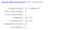
These specifications are similar in structure, so we want to share some ways of modeling the types of arrays and antenna elements directly. Figure 1 shows the interface to a model component that’s part of Phased Array System Toolbox and corresponds to Table 7.3-1 from 3GPP TR38.901 Version 14.0.0 Release 14. The phased.NRAntennaElement modeling component provides an interface to create a desired pattern that includes cross-polarized elements, beamwidth specifications, sidelobe levels, and the max gain and attenuation.
You can use this element to construct an NR antenna based on the 3GPP 38.901 standard. Figure 2 illustrates a plot of the antenna response as a function of azimuth angle at 6 GHz.
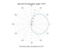
Figure 3 shows an example of this type of element with the antenna beamwidth set to 45 degrees in azimuth and 30 degrees in elevation.
element = phased.NRAntennaElement('Beamwidth',[45,30]);
The antenna definition can be used for quick analysis work. It also can be applied in an antenna array to form a more focused, steerable beam pattern in support of system-level simulations. We will provide some examples later, but let’s first describe a corresponding antenna array definition.
Figure 4 shows the phased.NRRectangularPanelArray model component from Phased Array System Toolbox that corresponds to Figure 7.3-1 from 3GPP TR38.901. This interface can be used to create a rectangular antenna array designed to meet the 3GPP TR 38.901 standard. Each panel is a heterogeneous array consisting of colocated antenna elements.
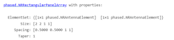
You can use the phased.NRAntennaElement in the phased.NRRectangularPanelArray to define the pattern of each element in the array. In addition, standard element types can be used for the antenna pattern. If you have a custom antenna pattern from a solver-based tool like Antenna Toolbox or from a measurement, it also could be directly imported.
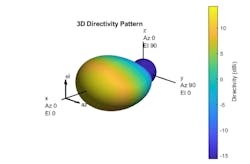
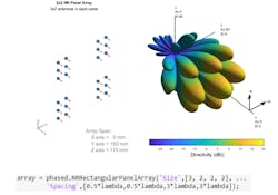
Figure 5 shows a 3D directivity pattern generated from phased.NRRectangularPanelArray with the phased.NRAntennaElement. The size of the array includes the number of elements in a panel (first two entries) and the number of panels in the array (last two entries). Spacing information is provided between elements (first two entries) and panels (last two entries).
Once an array is defined, the configured model component can be integrated into larger analysis functions and system-level simulations.
For example, Figure 6 shows how the pattern from the array can be used to configure the CDL channel model with the information generated by the ray-tracing analysis.
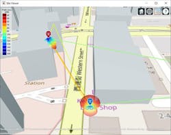
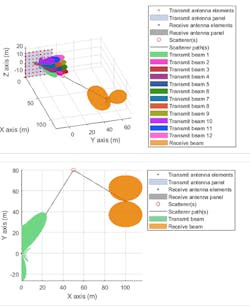
Figure 7 depicts the antenna array and corresponding pattern as part of a beam-sweeping and refinement application.
To learn more about the topics covered in this blog and explore your own designs, see the examples below or email me at [email protected]:
- NR SSB Beam Sweeping (Example): Learn how to employ beam sweeping at both the transmitter (gNB) and receiver (UE) ends of a 5G NR system.
- NR Downlink Transmit-End Beam Refinement Using CSI-RS (Example): Learn how to transmit multiple CSI-RS resources in different directions in a scattering environment and how to select the optimal transmit beam based on reference signal received power (RSRP) measurements.
- MIMO Communications Applications (Documentation): Learn how to model multiple-input, multiple-output communications systems using phased-array antennas and spatial-signal-processing algorithms.
- Design antenna elements and arrays using electromagnetic solvers (Documentation): Learn to design, analyze, and visualize antenna elements and antenna arrays.
See additional 5G, radar, and EW resources, including those referenced in previous blog posts.
Rick Gentile is Product Manager and Honglei Chen is Principal Engineer at MathWorks.
About the Author
Rick Gentile
Product Manager, Phased Array System Toolbox and Signal Processing Toolbox
Rick Gentile is the product manager for Phased Array System Toolbox and Signal Processing Toolbox at MathWorks. Prior to joining MathWorks, Rick was a radar systems engineer at MITRE and MIT Lincoln Laboratory, where he worked on the development of several large radar systems. Rick also was a DSP applications engineer at Analog Devices, where he led embedded processor and system level architecture definitions for high performance signal processing systems used in a wide range of applications.
He received a BS in electrical and computer engineering from the University of Massachusetts, Amherst, and an MS in electrical and computer engineering from Northeastern University, where his focus areas of study included microwave engineering, communications, and signal processing.
