Phased-Array Antenna Patterns (Part 5)—Beam Squint
>> Microwaves & RF Resources
.. >> Library: Article Series
.. .. >> Topic: Phased-Array Antenna Design
.. ... .. >> Phased-Array Antenna Patterns
Download this article in PDF format.
In previous parts of this series, we described how, when a wavefront approaches an array of elements, there’s a time delay between elements based on the wavefront angle θ relative to boresight. For a single frequency, the beamsteering can be accomplished by replacing the time delay with a phase shift. This works for narrow-band waveforms, but for wideband waveforms, where the beamsteering is produced by a phase shift, the beam can shift direction as a function of frequency.
Such a situation can be intuitively explained if we remember that a time delay is a linear phase shift vs. frequency. Thus, for a given beam direction, the phase shift required changes as a function of frequency. Or, conversely, for a given phase shift, the beam direction changes as a function of frequency. The concept of the beam angle changing as a function of frequency is called beam squint.
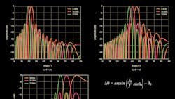
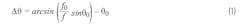
Also consider that at boresight, θ = 0, there’s no phase shift across the elements and therefore no means to produce any beam squint. Therefore, the amount of beam squint must be a function of angle, θ, as well as the frequency variation. Figure 1 shows an X-band example. In this example, the center frequency is 10 GHz, the modulation bandwidth is 2 GHz, and it’s apparent that the beam changes direction as a function of both frequency and the initial beam angle.
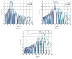
Beam squint can be calculated directly. Using Equations 1 and 2 from Part 4 of this series, the beam direction deviation, beam squint, can be calculated as:
This equation is shown graphically in Figure 2, in which the f/f0 ratio shown is intentional. The reciprocal of (f0/f) from the previous equation provides an easier way to visualize the change relative to a center frequency.
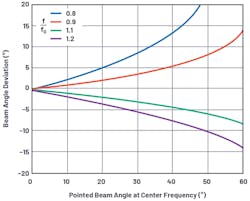
A few observations on beam squint:
- As the beam angle increases away from boresight, so too does the deviation in beam angle vs. frequency.
- A frequency below the center frequency causes a larger deviation than a frequency above the center frequency.
- A frequency below the center frequency moves the beam further away from boresight.
Beam-Squint Considerations
The beam squint, or deviation in steering angle vs. frequency, is caused by approximating a time delay with a phase shift. Implementing beamsteering with true time-delay units doesn’t have this problem.
With the beam squint problem so clearly visible, why would anyone use a phase shifter over a time-delay unit? Typically, this comes down to design simplicity and IC availability of phase shifters vs. time delays. Time delays are implemented in some form of transmission line and the total delay needed is a function of the aperture size. To date, most available analog beamforming ICs are phase-shift-based, but families of true time-delay ICs are emerging, and these may become much more common for phased-array implementations.
In digital beamforming, true time delay can be implemented in the DSP logic and digital beamforming algorithms. Therefore, a phased-array architecture in which every element is digitized would lend itself naturally to overcome the beam-squint problem, while also providing the most programmability. However, the power, size, and cost of such a solution can be problematic.
In hybrid beamforming, there’s a combination of analog beamforming for subarrays followed by digital beamforming for the full array. This can offer some natural beam-squint mitigation worth considering. Beam squint is only subject to the subarray, which is a much wider beamwidth, so it’s more tolerant to a beam-angle deviation. Thus, if the subarray beam squint is tolerable, then the hybrid beamforming architecture can be implemented with phase shifters in the subarrays, followed by true time delay in the digital beamforming.
Previously in this series, we introduced beam pointing and the array factor. We then introduced imperfections of grating lobes and beam squint. In the coming articles, we will discuss tapering as a method to reduce sidelobes, and provide insight into the impact of phase-shifter quantization errors.
Peter Delos is Technical Lead and Bob Broughton is Director of Engineering for Analog Devices' Aerospace and Defense Group, and Jon Kraft is Senior Staff Field Applications Engineer at Analog Devices.
References
Balanis, Constantine A. Antenna Theory: Analysis and Design, third edition. Wiley-Interscience, 2005.
Longbrake, Matthew. True Time Delay Beamsteering for Radar. 2012 IEEE National Aerospace and Electronics Conference (NAECON), IEEE, 2012.
Mailloux, Robert J. Phased Array Antenna Handbook, second edition. Artech House, 2005.
O’Donnell, Robert M. “Radar Systems Engineering: Introduction.” IEEE, June 2012.
Skolnik, Merrill. Radar Handbook, third edition. McGraw Hill, 2008.
>> Microwaves & RF Resources
.. >> Library: Article Series
.. .. >> Topic: Phased-Array Antenna Design
.. ... .. >> Phased-Array Antenna Patterns
About the Author
Peter Delos
Technical Lead, Aerospace and Defense Group, Analog Devices
Peter Delos is a technical lead in the Aerospace and Defense Group at Analog Devices in Greensboro, N.C. He received his BSEE from Virginia Tech in 1990 and MSEE from NJIT in 2004. Peter has over 25 years of industry experience, with most spent designing advanced RF/analog systems at the architecture level, PWB level, and IC level. He’s currently focused on miniaturizing high-performance receiver, waveform generator, and synthesizer designs for phased-array applications.
