GNSS Signals Are Used For Frequency Standards
This file type includes high resolution graphics and schematics when applicable.
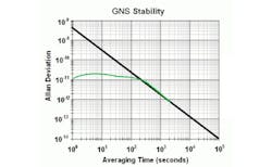
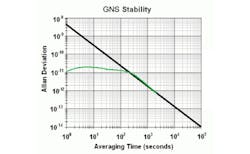
The proliferation of global navigation satellite systems (GNSSs) could enable the implementation of a higher-quality frequency standard than the costly cesium atomic clock. This new system uses the base technology of the Global Positioning Satellite (GPS) systems to attain a highly precise physical positions. In doing so, it provides frequency standards with accuracy better than 6E-13 over 24 hrs. Delving into the details of such a system, PTF provides an application note titled “High Performance GNSS Disciplined Frequency Reference Standards.”
To detect the precise position of a GNSS receiver, a connection is needed for a minimum of four satellites. This information also can be used to derive accurate timing data, which can be used to control an oscillator’s stability. There are two primary methods for generating the timing data: using the 1 pulse per second (1-PPS) signal or carrier-phase-disciplined-oscillator (CPDO) method. A hybrid of both methods would produce the highest accuracy. But the cost and complexity of a CPDO make it less viable than cleverly solving the accuracy issues associated with the 1-PPS method.
For its part, the 1-PPS method is highly stable over time. Depending on the resolution of the oscillator signal, however, it may shift each cycle relative to the oscillator’s phase. Although an oven-controlled crystal oscillator (OCXO) has a very stable phase-noise figure, the OCXO degrades over time in accuracy. If both a 1-PPS system and OCXO are combined effectively with a control loop, a highly accurate and stable frequency reference can be designed.
To align the 1-PPS signal with the oscillator’s signal, one approach is to use the OCXO’s base frequency and divide it down to a single cycle per second. But this method introduces inaccuracy based upon the phase noise of the oscillator. Even with clever half-clock cycle techniques, a 5-ns error from a 100-MHz clock is not accurate for measuring 10-ns saw-tooth granularity errors. PTF claims to resolve this issue by using an interpolator charging capacitor technique, which reportedly enhances resolution on the quantization error by 1000 times. This would produce a phase measurement resolution of 0.1 ns, effectively synchronizing the two signals.
Using this technique and a simple controller, the company touts the potential for an RF signal with stability greater than 2E-11, phase noise beyond -125 dBc at 10 Hz offset from the carrier, and accuracy of greater than 1E(-12) over 24 hrs. The quality of the RF-controlled signal could be degraded by other factors, such as poor power supplies, low-grade buffer amplifiers, poor analog/digital layout, and insufficient grounding. Thus, those factors also should be considered in the design.
PTF, 50L Audubon Rd., Wakefield, MA 01880; (781) 245-9090
This file type includes high resolution graphics and schematics when applicable.
About the Author
Jean-Jacques DeLisle
Jean-Jacques graduated from the Rochester Institute of Technology, where he completed his Master of Science in Electrical Engineering. In his studies, Jean-Jacques focused on Control Systems Design, Mixed-Signal IC Design, and RF Design. His research focus was in smart-sensor platform design for RF connector applications for the telecommunications industry. During his research, Jean-Jacques developed a passion for the field of RF/microwaves and expanded his knowledge by doing R&D for the telecommunications industry.
