Pinpoint the High-Frequency Resistance of Toroidal Windings
Relatively accurate formulas exist for calculating the high-frequency (HF) resistance of a solenoidal inductor (accurate to between 5% and 10%). Historically, however, the approximations for toroidal inductors have been unmanageably inaccurate when the wiring diameter is greater than or equal to the skin depth.
To help conquer this problem, Micrometals produced an application note that discusses the simulation and modeling of toroidal windings at high frequencies. The note, “Calculating The High Frequency Resistance of Single and Double Layer Toroidal Windings,” details the development of formulas and graphs for accurately calculating the resistive losses of single-layer toroidal windings.
The multidimensional complexity of a toroidal winding system goes beyond the scope of an analytical technique. With the use of electromagnetic (EM) finite-element-analysis technology, though, many experiments can be run on various toroidal-winding configurations. In addition, it’s possible to model and describe the parameter interactions using an adapted formula. The note describes the necessary assumptions for this process, such as the consideration of precision manufacture. After all, non-uniformities would unreasonably increase complexity.
The formulas for the single-layer windings also assume a generously sized wire diameter. It must be sufficiently large to keep the separation distance between the windings and the magnetic core’s surface to less than 4%. Many of the parameters that define the effects of core proximity and eddy current are complex derivatives of other parameters. As a result, two correction factors from the simulation study are used instead of derived formulas.
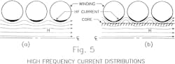
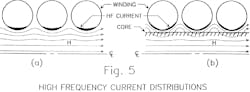
When comparing the two-layer toroidal winding versus the singular, the former results in a significantly higher resistance at high frequencies. Such increased resistance is a product of the high-frequency current riding along the wire surface, which creates eddy-current losses in the secondary layer. These losses offset the lower-conduction losses that stem from having greater conductive surface area.
In conclusion, the note shows that the single-layer toroidal winding suffers the least loss with solid conductors. Spacing the round wires does not reduce the eddy-current losses enough to counteract the total loss per winding width.
Micrometals Inc., 5615 E. LA Palma Ave., Anaheim, CA 92807-2109, (714) 970-9400
About the Author
Jean-Jacques DeLisle
Jean-Jacques graduated from the Rochester Institute of Technology, where he completed his Master of Science in Electrical Engineering. In his studies, Jean-Jacques focused on Control Systems Design, Mixed-Signal IC Design, and RF Design. His research focus was in smart-sensor platform design for RF connector applications for the telecommunications industry. During his research, Jean-Jacques developed a passion for the field of RF/microwaves and expanded his knowledge by doing R&D for the telecommunications industry.
