RF/mmWave Filters Simplify Spectrum Management
Members can download this article in PDF format.
What you'll learn:
- Why the ubiquitous RF/MW filter is essential in today's high-frequency systems.
- Attributes of waveguide and coaxial filters.
- Who designs and manufactures these filters?
- The growing need to miniaturize these devices.
The electromagnetic (EM) spectrum may be wide, but it’s not unlimited, and engineers depend on high-frequency filters to help keep EM signals in place. Filters gain in importance as the applications within RF, microwave (MW), and even millimeter-wave (mmWave) frequencies continue to expand, protecting signals of interest from noise and preventing nearby signals from causing unwanted interference. High-frequency filters are available in many technologies and package styles, and this special report facilitates the task of finding a filter that enables many EM signals to coexist.
RF/MW filters are frequency-control components that help squeeze the greatest number of applications into the least amount of spectrum possible. They can be fixed or tunable, active or passive. They’re simple in nature, designed to transfer some signals and stop others, such as for a radio channel. Such filters can be implemented on a printed circuit board (PCB) with essential lumped elements of a resistor (R), inductor (L), and capacitor (C), and they shrink in size relative to the wavelength of the frequencies of interest.
An RF/MW filter with an ideal signal-transfer function exhibits minimal passband distortion and high attenuation in the stopband or bands. Physically, a filter can handle as much signal power as possible in the smallest of packages. With modern trends pushing toward RF/microwave filters with reduced size, weight, and power (SWaP), filters in drop-in and surface-mount-technology (SMT) packages have been gaining in popularity as they continue to increase in frequency and power-handling capabilities.
High-frequency filters perform spectral management via four basic response types: low pass, high pass, bandpass, and band-reject filters (also known as notch filters). (An easy-to-follow blog from Mini-Circuits, “Understanding Lumped Element Filters,” reviews the four filter responses and how they can be implemented with passive circuit elements.)
In addition, the “Terms & Definitions” section of the online 136-page product catalog from K & L Microwave shares that company’s long experience and expertise in the design and fabrication of custom RF and microwave filters for aerospace, defense, and commercial applications. It provides text-book-like explanations of high-frequency filter terms and characteristics.
A high-frequency filter’s response includes regions with minimal loss versus frequency and spectral regions where high attenuation is applied to signals. Changeovers from regions with no loss to regions with high signal rejection are typically denoted by a single 3-dB or half-power point for lowpass and high-pass filters and two 3-dB points for bandpass and band-stop filters. A filter’s center frequency typically divides a bandpass filter’s 3-dB low-loss passband and a band-stop filter’s 3-dB high-rejection stopband.
Bandpass and band-reject filters are also defined by their qualify factor (Q), which is equal to the filter’s center frequency (f0) divided by its 3-dB bandwidth. Q values rise for filters at increasing operating frequencies with narrower passbands: the higher the Q, the narrower the passband. Operating conditions will impose specific sets of performance requirements on RF/MW filters, including how they process signal amplitude, phase, and group delay as functions of temperature.
High-frequency filters are evaluated in terms of standard performance parameters. These include passband insertion loss, stopband rejection, selectivity (how quickly the response changes between low loss and high rejection), power-handling capability, return loss (or VSWR), group delay (also known as envelope delay), and temperature effects. Filters can suffer distortion in amplitude, phase, and group delay (nonconstant delay with frequency) with changes in temperature, whether due to the environment or from heat dissipated when operating at high power levels.
A filter’s characteristic impedance, typically 50 Ω for high-frequency applications, can be determined by L/C, where L is the filter’s total series inductance and C is its total shunt capacitance. High-frequency filters should closely match an application’s source and load impedances at input and output ports, respectively, to maintain response linearity and minimize some forms of distortion, such as passive intermodulation (PIM) distortion.
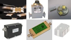
High-frequency filters are available from many suppliers (see table) in a variety of technologies and package styles. Performance levels can be customized when standard models don’t meet the requirements of an application.
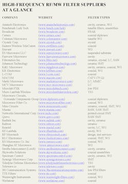
(For clickable versions of the links in the table, download the PDF version of this article. Link is at the top of this page.)
Making Filters Fit
As electronic designs are made smaller and more power-efficient, miniaturization remains an ongoing trend for high-frequency filters, although larger filters are still required at higher power levels.
Waveguide Filters
Waveguide filters are one of the larger types of high-frequency filters. The cavity contained within the physical structure provides the physical dimensions required for conductance of EM fields at specific wavelengths and frequencies. The size of a rectangular waveguide (WR) is identified by number, with decreasing numbers signifying smaller wavelengths and higher frequencies, such as WR-28 for 26.5 to 40.0 GHz and WR-10 for 75 to 110 GHz.
Waveguide (WG) bandpass filters are commonly used in higher-power systems such as communications transmitters and radars. They’re capable of low insertion loss and return loss (VSWR) to minimize heat at high power levels.
WG bandpass filters are available from numerous suppliers for applications typically reaching 110 GHz. Pasternack, for example, maintains a large inventory of WG bandpass filters in different sizes and frequencies for applications such as test, where a component may be needed without delay. Mini-Circuits has partnered with Virginia Diodes to develop rectangular WG bandpass filters through mmWave frequencies in addition to high-frequency filters based on other technologies, including lumped-element, microstrip, and stripline filters.
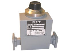
Long-time supplier of coaxial and waveguide components, Coleman Microwave, offers WG filters in fixed and tunable forms. Fixed filters cover a total frequency range of 4.40 to 16.95 GHz, all in packages measuring 7.50 × 2.50 × 4.375 in.
Bandpass models FWB1050 and FWD1050 both operate from 9.6 to 10.5 GHz with 3-dB bandwidths of 17 MHz. The former has a 40-dB passband of 200 MHz with a maximum passband 3-dB insertion loss of 1.60 dB, while the latter has a 40-dB passband of 70 MHz with a maximum passband 3-dB insertion loss of 2.30 dB. Thus, specifiers can select the abruptness of attenuation around the center frequency.
For satellite communications (satcom) systems, the eBPF-C series of C-band WG bandpass filters from Norsat International is designed to install between an antenna feed and receiver low-noise block downconverter (LNB). This helps minimize interference from terrestrial signal sources in radar and 5G wireless communications systems.
One member of the series, model eBPF-C-1, has maximum insertion loss of 1.4 dB within a passband of 3.7 to 4.2 GHz, with at least 60-dB rejection at 3.682 GHz and at least 25-dB rejection at 4.230 GHz and above. There’s a 3-ns maximum group delay variation within any ±0.5-MHz span in the passband. The filter measures 7.28 × 3.94 × 2.79 in (185 × 199 × 71 mm) and weighs 970 g.
To further save space in a system, the company also integrates LNBs with WG filters in a single, slightly larger package. When adapting WG filters within a system using coaxial and other component configurations, companies such as Ducommun and Lieder Development offer suitable interconnections from 18 to 110 GHz.
Coaxial Filters
Coaxial-packaged filters still represent the greatest number of high-frequency filters currently in use. They house many technologies between the connectors, including bulk-acoustic-wave (BAW), cavity, lumped-element (LC), microstrip, stripline, and surface-acoustic-wave (SAW) filter structures.
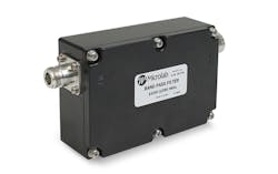
RF-Lambda, for example, offers WG filters to 110 GHz, but also a variety of coaxial filters. Its model RBPF33G04G06 is a suspended-substrate-stripline bandpass filter in compact enclosure with female input and output connectors. It has a passband of 4.2 to 5.7 dB with 0.85-dB typical insertion loss and 1.50:1 VSWR. Lower stopband rejection is typically 52 dB from dc to 3.4 GHz and upper stopband rejection is typically 60 dB from 6.9 to 9.5 GHz.
A good match for radar and wireless communications, the filter meets MIL-E-5400 standards and comes in a hermetic housing as an option. It handles as much as 15-W CW input power over an operating temperature range of −55 to +85°C.
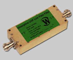
The compact filter handles the heat with an aluminum housing measuring 4.20 × 1.75 × 1.13 in. and a choice of connectors: two female N, two SMA, or one of each. Passband insertion loss is low, typically 0.5 dB, while stopband rejection is a respectable 45 dB. The low pass has an operating temperature range of −55 to +75°C.
In terms of high coaxial power, cavity bandpass filter model RCBPF-900-920M-Sf-65W-c14 from Raditek handles 65 W or more signal power across a 20-MHz passband centered at 910 MHz. It achieves the high power-handling capability via extremely low passband insertion loss of 0.4 dB or less, yet still provides 40 dB or more stopband rejection, such as for an upper stopband range of 1,800 to 2,700 MHz. The RoHS-compliant filter is equipped with SMA female connectors.
Insertion loss across the passband is no more than 0.7 dB with low 20-ns group delay. This enables power-handling capability of 100-W CW power and 3-kW peak power with pulsed signals for a coaxial package with N connectors measuring 4.9 × 3.3 × 1.6 in. (124.5 × 84.0 × 40 mm) and weighing 1.9 lbs. (0.86 kg). The compact filters achieve 80-dB rejection across a lower stopband from 100 to 600 MHz and the same high rejection across an upper stopband of 1,520 to 6,600 MHz.
With its long history of RF/MW filter design and development, K & L Microwave backs its designs with some of the industry’s most comprehensive testing, using the latest microwave and mmWave signal generators and analyzers and comprehensive environmental and temperature test chambers. Offering drop-in, coaxial, and waveguide filters from RF through mmWave frequencies in all high-frequency filter responses, the company also has developed a unique software tool called Filter Wizard. Available online, it helps users more quickly and effectively meet the filtering needs of a particular application.
Getting Smaller
As electronic products are being designed and manufactured for greater mobility and miniaturization, RF/MW filters are among the many components shrinking in size (where signal power levels will permit it) and fitting into SMT configurations. Especially as filters are moving higher into mmWave frequencies, filter suppliers are exploring the use of different material substrates to enable high performance at high frequencies and in small packages.
The thermoplastic LCP material can be applied to single- and multiple-layer SMT filters. It has a low dielectric constant (3.16) and dissipation factor (0.0045) that make it a candidate for low-loss miniature filters to 110 GHz. In addition, LCP’s low material coefficient of thermal expansion (CTE) of 17 ppm/°C supports stable performance with temperature.
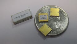
Ceramic materials from Johanson Technology have paved the way for tiny SMT bandpass filters for Wi-Fi 7 and 802.11ax/be wireless applications. Though in packages measuring 0.217 × 0.126 × 0.087 in. (5.50 × 3.20 × 2.20 mm), the filters can handle as much as 3 W of signal power. The filters are available with low-loss passbands of 5,150 to 5,835 MHz, 5,170 to 5,825 MHz, 5,925 to 7,125 MHz, and 5,945 to 7,125 MHz
For instance, the model 5492BP46A0685001E has typical insertion loss of 2.9 dB from 5,150 to 5,785 MHz and 4.2 dB across the upper end of its passband from 5,785 to 5,835 MHz. It rejects signals by 60 dB below the passband from dc to 2,500 MHz and by 48 dB from 2,500 to 4,000 MHz and by 43 dB above the passband from 5,925 to 5,990 MHz, with rejection rising to at least 45 dB to 17.5 GHz. The compact filters are designed for operating temperatures from −40 to +85°C.
Synergy Microwave Corp., perhaps best known for its low-noise oscillators and frequency synthesizers, supports its signal sources with lines of crystal low-pass, high-pass, and bandpass filters in low-profile SMT packages.
Its model FNS-10.7 bandpass filter has a center frequency at the reference of 10.7 MHz with 3-dB passband of 10.2 to 11.2 MHz and maximum passband insertion loss of 1.7 dB. The low loss and passband VSWR of 1.50:1 account for its capability to handle as much as +30 dBm (1 W) signal power in a package measuring just 0.945 × 0.945 × 0.440 in. The SMT filter has an operating temperature range of -40 to +85°C.
Employing standard substrate materials such as alumina, Networks International Corp. has succeeded in shrinking thin-film high-frequency filters from 1 to 26 GHz with bandwidths from 1% to 60% into SMT packages with low 0.05-in. heights.
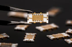
Packing its BAW filter technology into a miniature SMT housing, Qorvo has targeted IFF applications centered at 1,090 MHz with its model 880374 bandpass filter. The package measures just 3.74 × 2.59 × 0.889 mm but employs a sapphire base with alumina lid for hermeticity. For ease of use, it can be installed on a PCB without impedance-matching components.
The bandpass filter has a 22-MHz-wide 3-dB passband centered at 1,090 MHz with 3-dB maximum insertion loss across the passband and 40-dB points at 1,073 and 1,107 MHz. The tiny filter can handle as much as+24-dBm CW RF input power and as much as +42 dBm for 200-ms pulses across an operating temperature range of −40 to +85°C.
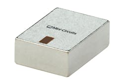
The LTCC material system also forms the foundation for the company’s model BFCQ-4302+ mmWave bandpass filter in a 1008 SMT enclosure measuring just 2.5 × 2.0 mm but capable of handling 1-W signal power across a passband of 36.5 to 50.0 GHz. Passband insertion loss is typically 2 dB with an upper stopband that extends to almost 70 GHz. Lower stopband rejection is 20 dB or more from 0.1 to 27.0 GHz while upper stopband rejection is typically 15 dB from 57.3 to 59.0 GHz and typically 10 dB from 59 to 67 GHz.
And for circuit designers who may not have finalized a filter’s characteristics for a design, Mini-Circuits offers SMT thru-lines allowing signals to pass that point in the circuit with minimal loss and take the place of an 0805 LTCC filter until its required characteristics are known.
High-frequency filters will continue to shrink in size as operating frequencies rise, so package sizes can be expected to continue to shrink. As wireless networks such as 5G and 6G develop at these higher (mmWave) frequencies, filters will play key roles in ensuring reliable communications and prevent interference from a growing number of devices on 5G/6G networks, such as Internet of Things (IoT) devices and “flocks” of drones with sensors that rely on wireless connectivity for Internet access.
About the Author
Jack Browne
Technical Contributor
Jack Browne, Technical Contributor, has worked in technical publishing for over 30 years. He managed the content and production of three technical journals while at the American Institute of Physics, including Medical Physics and the Journal of Vacuum Science & Technology. He has been a Publisher and Editor for Penton Media, started the firm’s Wireless Symposium & Exhibition trade show in 1993, and currently serves as Technical Contributor for that company's Microwaves & RF magazine. Browne, who holds a BS in Mathematics from City College of New York and BA degrees in English and Philosophy from Fordham University, is a member of the IEEE.
