Tips on Selecting High-Frequency mmWave/RF Cables for Defense Applications
This article is part of the TechXchange: Defense Electronics.
Members can download this article in PDF format.
What you’ll learn:
- Challenges of mmWave technology in defense applications.
- What should aircraft system architects & engineers be concerned about?
- Factoring connections for inside-the-box (B-Kit) and between-the-boxes (A-Kit).
- How to ensure mission-critical success and peace of mind?
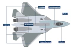
Mission success, aircraft survivability, and personnel safety depend on critical defense systems such as radar warning receivers (RWRs) that deliver threat notifications to pilots and other system operators. In addition, Command, Control, Communication, Computers, Cyber, Intelligence, Surveillance and Reconnaissance (C5ISR) systems must reliably provide global situational awareness using less aperture and space.
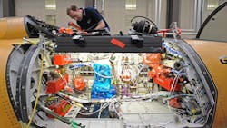
The components of these critical systems are dispersed all over the aircraft for tactical or practical reasons (Fig. 1). Many microwave/RF assemblies, power wires, and high-speed data cables are routed throughout the airframe to connect these components.
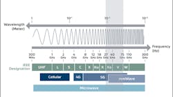
The U.S. Department of Defense (DoD) continues to increase its frequency utilization throughout the electromagnetic spectrum (EMS), and the next big expansion trend is technology in the millimeter-wave (mmWave) portion of the spectrum. This technology operates at Ka-band frequencies from 27 to 40 GHz and V-band frequencies from 40 to 75 GHz, providing faster connectivity and data exchange for communications and mission systems (Fig. 2).
As threats emerge in the mmWave frequency range, electronic warfare (EW) and aircraft survivability equipment (ASE) systems for the DoD must keep pace by adding higher-frequency aircraft components, which can cause serious implementation challenges.
Connectivity is a significant challenge when implementing mmWave technology in aircraft. RF coaxial-cable assemblies are required to transmit mmWave analog signals within and between aircraft components. These critical interconnects are susceptible to damage during challenging installation and mission conditions, and operating at mmWave frequencies adds a higher level of complexity to the mix.
Concerns for Aircraft System Architects and Engineers
RF cables and assemblies in DoD aircraft are exposed to vapor, fuel, and other hazardous contaminants. These cable assemblies must survive typical aircraft conditions to avoid compromising mission-critical systems. Commonly used semi-rigid or RF cables that aren’t ruggedized and vapor-sealed should not be used in airframes or between-the-boxes as they will not perform reliably in these harsh conditions.
Furthermore, flexing, bending, pulling, and clamping during cable routing and installation can damage or degrade the performance of RF cables before the first flight. Once airborne, RF cables experience repeated shock and vibration, extreme pressure and temperature changes, and harsh contaminants.
It’s important to note that damage to non-ruggedized RF cables may not be noticed immediately after installation, depending on the testing conducted. However, repeated stress to RF cables during flights over time can lead to compromised signal integrity, resulting in unreliable communications, degraded self-protection systems, lower mission completion rates, and increased lifecycle costs.
Durability and Size
Connecting standard or non-ruggedized RF cables to avionics in crowded airframe areas requires bending, twisting, and pulling during routing in tight spaces or against sharp edges, which can cause abrasions, splits, or cracks. In addition, repeated shock, constant vibration, extreme temperatures, harsh fuels and chemicals, and routine maintenance can compromise these cables.
Unpressurized areas of the aircraft are equally challenging. High humidity, rapid pressure changes, condensation, liquids, and vapors can permeate improperly sealed RF cables and alter their dielectric insulator, causing uncontrolled impedance and performance changes.
Engineers also must find ways to optimize size, weight, and power (SWaP) to increase fuel efficiency and maximize available payload. Smaller, lighter-weight, and more flexible cable designs can help with SWaP issues and complement next-generation avionics that will soon be required in fifth-generation aircraft and beyond.
Installed Performance
According to an independent study conducted by W. L. Gore & Associates (Gore), the aerospace industry widely accepts frequently replacing RF cables damaged during installation and operation. Often, damage to RF cables can go undetected because nothing might be physically detected on the cables’ outer jacket.
Gore believes the key to reducing costs and guaranteeing reliability before and after installation and over time in aircraft is choosing RF cables tested to survive real-world conditions and qualified to meet stringent industry standards, such as the MIL-T-81490. However, based on Gore’s experience dealing with airframe installation challenges, it’s not enough to just claim that an RF cable is qualified to MIL-T-81490 requirements.
To demonstrate the reliability of its RF and airframe cable assemblies, Gore designed a cable installation simulator that mimics real-world conditions to ensure its products do what they say they will do consistently and reliably, even in harsh conditions. The simulator showed how non-ruggedized RF airframe cables could quickly and easily fail in mechanical and electrical performance during routing (Fig. 3).

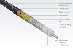
The simulator proves how important it is for equipment manufacturers and airframe integrators to specify rugged, vapor-sealed, and electrically reliable RF cables with optimal SWaP, particularly when connecting higher-frequency mmWave components (Fig. 4).
Factoring Connections for Inside-the-Box (B-Kit) and Between-the-Boxes (A-Kit)
You may not need internally ruggedized, vapor-sealed RF cable assemblies for interconnects inside electronic line replaceable units (LRUs), such as processors, receivers, amplifiers, and antennas for C5ISR, ASE, and EW systems. However, these cable assemblies are critical to mmWave systems and operate in challenging environments.
RF cables must be flexible and small enough. Bend radii should be down to 0.1 in. (2.54 mm) for routing in extremely tight airframe spaces while maintaining reliable, repeatable electrical performance.
In addition, equipment designers and manufacturers have implemented a wide variety of industry-standard and custom RF connector interfaces between the backplanes, daughtercards, and front panels of LRUs for systems that operate in low-frequency bands.
However, most of the connector interfaces used in these LRUs were designed for density without considering the future operational needs at frequencies higher than X-band or Ku-band. Thus, the majority of RF cable assemblies available in the market today aren’t capable of transmitting a signal at mmWave frequencies.
Only a few manufacturers have the expertise to design, build, and terminate mmWave cable assemblies. Many systems throughout the aircraft include cables from numerous suppliers. While these suppliers use standard interfaces, most aren’t impedance-matched and designed adequately for operation at higher mmWave frequencies. Cross-mating interfaces from multiple suppliers may impact performance reliability and limit the ability of ASE and EW systems to meet their mission objectives.
Therefore, a single-source supplier offering cable assemblies for both inside-the-box (B-Kit) and between-the-boxes (A-Kit) is highly recommended to provide true mate-ability, reduced impedance discontinuities, and optimal performance in mission-critical systems.
For example, VITA and SOSA standards can be referenced for RF connector interfaces inside and outside LRUs. The VITA 67.3 standard recommends sub-miniature push-on micro (SMPM) and sub-miniature push-on sub-micro (SMPS) interfaces for high-density backplanes and daughtercards operating at frequencies up to 60 GHz.
For connectivity between LRUs, the SOSA standard recommends using MIL-DTL-38999, size-25 connectors. These connectors can be populated with up to 19 RF lines terminated with size-12 SMPM contacts capable of transmitting signals at frequencies up to 50 GHz. Acquiring this complete link of airframe and inside-the-box cable assemblies from a single-source supplier would help achieve a continuous, reliable signal transmission at frequencies up to 50 GHz from the antenna to the main processor chip.
Ensuring Mission-Critical Success
The aerospace industry recognized the reliability challenges of frequently replacing RF assemblies due to damage during installation or operation, even before adding mmWave components. For reliable performance in critical aircraft systems, select rugged yet flexible airframe assemblies that deliver lifetime performance by withstanding rigorous routing, maintenance activities, and flight conditions.
Therefore, it’s crucial to use ruggedized, vapor-sealed cable assemblies for airframe installation rather than traditionally designed RG or semi-rigid assemblies. Whether your system is operating at 2, 18, or 50 GHz, selecting RF assemblies tested and qualified to survive real-world environments is the only way to ensure a fit-and-forget solution with optimized SWaP (Fig. 5).
Furthermore, it’s imperative that aircraft system architects and engineers fully understand and consider mechanical durability, electrical reliability, and connector options when choosing an RF cable for mmWave components. And factoring in the complete system from inside-the-box and between-the-box is vital during the initial design phase.
Purchasing RF cable assemblies from the same supplier throughout the entire system can impact performance reliability. Considering the complete system during the initial design phase can save the total cost of ownership to the military, enhance system functionality at higher frequencies, and reduce aircraft maintenance and downtime for mission-critical success and peace of mind.
For additional information, read Gore’s white papers, “Reducing Life Cycle Costs with Reliable Airframe Microwave Assemblies,” and “Proving Installed Performance of Airframe Microwave Assemblies.” Also, visit the website to learn more about Gore’s microwave airframe assemblies.
Read more articles in the TechXchange: Defense Electronics.
About the Author
Jerico Sabas
Application Engineer, W. L. Gore & Associates
Jerico Sabas earned an MS in Electrical and Computer Engineering with a concentration in RF technology from the University of Delaware. He has over 15 years of experience supporting multiple RF systems. Today, he’s a senior application engineer with Gore focused on RF connectivity solutions for the aerospace and defense market.
