Mitigate Interference Using mmWave Arrays with Integrated Filtering

Members can download this article in PDF format.
What you’ll learn:
- The challenges posed by interference from adjacent mmWave bands.
- How an LTCC 2x2 antenna array with integrated BPFs can mitigate interference.
- The critical nature of feeding networks in antenna arrays.
The 5G New Radio (NR) technology rollout has begun worldwide. Since the 3GPP standardized Release 15 rolled out in late 2018, 5G NR has primarily targeted three different use cases: enhanced mobile broadband (eMBB), massive machine-type communication (mMTC), and ultra-reliable low-latency communication (URLLC).
Unlike previous mobile network generations, 5G NR will not completely replace 4G LTE. Rather, it will coexist with the established 4G LTE network to seamlessly provide a superior user experience. Release 16, which came out in July of 2020, and the upcoming Release 17 are both intended to enhance 5G NR in terms of capacity, coverage, latency, and more.
Millimeter-wave (mmWave) technology is an essential aspect of the 5G mobile network, with massive data capacity demand being the primary driving factor to accelerate 5G mmWave implementation. mmWave in 5G NR, known as Frequency Range 2 (FR2, 24.25 GHz to 52.6 GHz), provides superior channel bandwidth, which enables significantly higher data rates and network capacity compared with sub-6-GHz (FR1) 5G systems.
But 5G mmWave technology has its downside, too: It suffers from high propagation path losses and poor penetration through obstructions, which lead to reduced coverage. This fact has mandated breakthroughs in antenna-array beamforming techniques.
Beamforming antenna arrays combine multiple antenna-element signals into a concentrated beam. The beam can be steered in a desired direction by weighting the magnitude and adjusting the phase of individual antenna-element signals. Rather than broadcasting in all directions like traditional antennas, the concentrated beam yields high directivity and antenna gain by complex beamforming configurations that effectively improve the mmWave coverage.
However, interference from adjacent mmWave bands utilized by network operators is critical in complex multi-cell and multi-user environments. A small cell can simultaneously communicate with multiple users via different beams formed by beamforming antenna arrays. Thus, the adjacent beams within the same cell may cause interference for individual users. Meanwhile, users within a given cell’s coverage may get adjacent beam interference formed by neighbor cells as well. Furthermore, adjacent to allocated 5G mmWave licensed frequency bands, multiple existing systems/services also can interfere with 5G systems, such as the Earth Exploration Satellite Service (EESS) that operates from 23.6 to 24.2 GHz.
To mitigate all unwanted interference, one promising solution is to use bandpass filters (BPFs) placed physically in series to individual beamforming antenna-array elements to block interference. This article introduces and provides an in-depth overview of a novel 28-GHz, 2x2 antenna array with integrated BPFs.
Design Considerations
Unlike other standard antenna-array structures, the 28-GHz (n257: 26.5 GHz~29.5 GHz), 2x2 antenna array consists of 2x2 dual-polarized antenna elements as well as eight integrated BPFs for the same frequency range. Dual-polarized antenna arrays are a necessity for 5G mmWave massive multiple-input, multiple-output (mMIMO) systems to enhance the channel capacity and spectral efficiency.
As shown in Figure 1, the overall structure separates into two sections, with the antenna-array structure sitting atop the BPF structured section. Each individual dual-polarized antenna element is designed with dual feeds, a horizontal polarization feeding port, and a vertical polarization feeding port, with each port having a respective series BPF to remove unwanted interference. This vertical structure enables the shortest connection between each BPF and antenna element, effectively minimizing the parasitic inductance to maintain the lowest overall insertion loss.
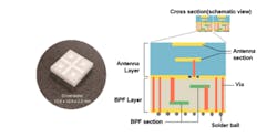
The basis of the featured 28-GHz, 2x2 antenna array is low-temperature, co-fired ceramic (LTCC) technology. LTCC is a multi-layer, glass ceramic substrate co-fired with low-resistance silver (Ag) conductors at relatively low firing temperatures (around 900°C), which is below the melting point of the silver.
Multi-layer design flexibility and low material dielectric loss are key advantages of LTCC technology. Two distinct and optimized ceramic materials are developed and co-fired into one homogeneous multi-layer package. That approach offers:
- Dielectric constant around 4 at 28 GHz for the antenna array.
- Dielectric constant around 9 at 28 GHz for integrated BPFs.
- 2 ppm/K temperature coefficient of frequency (TCF) enables ±0.04% frequency shifting at 28 GHz from −40 to 85°C (tested by individual 28-GHz BPF).
- 7.6-ppm/K relative low coefficient of thermal expansion (CTE).
- 3 W/m × K thermal conductivity allows great thermal stability and robustness.
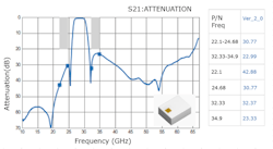
TDK debuted the first mass-produced, multi-layer ceramic 28-GHz BPF (P/N: MMCB2528G5T-0001A3) in 2019. The device offers a typical low insertion loss of less than 1 dB and excellent out-of-band rejection. The discrete 28-GHz BPF frequency response is shown in Figure 2 and this BPF structure was leveraged into the new 2x2 antenna array.
Individual antenna elements are configured to implement stacked patch structures, with each of the two stacked patches covering a sub-band to overcome the single patch antenna’s bandwidth limitation. The upper patch is referred to as the parasitic patch and the lower patch, which is located above the ground plane and connects to a feeding line, is used as a driven (input) patch. The upper and lower patches resonate at different frequencies, with electromagnetic coupling from the lower patch exciting the upper patch to obtain the desired wideband frequency response.
The influence of inter-element spacing between two adjacent antenna elements must be considered in antenna-array design. To reduce the antenna-array design complexity, we implemented a constant equalized inter-element spacing approach.
When the inter-element spacing exceeds half of the signal’s wavelength, grating lobes will become prevalent and have unwanted strong radiation patterns in directions other than the desired main lobe. To avoid these grating lobes, antenna inter-element spacing is designed to be close to the half wavelength (λ/2).
However, at the same time, mutual coupling influences exist between the adjacent antenna elements, which can’t be ignored—their impact on performance increases as the inter-element spacing decreases. Individual antenna-element radiation patterns depend not only on their own excitation, but also on electromagnetic (influence) interaction from neighboring antenna elements. The fact that mutual coupling also influences the input impedance of each individual antenna element is intuitive and function of the inter-element spacing as well.
In this case, the input impedance is the active impedance of each individual antenna element in the array when all antenna elements are excited. Therefore, the active impedance of each individual antenna element is given by the sum of its own impedance plus mutual impedances caused by proximity to the neighboring excited antenna elements.
To compensate for the mutual coupling effect, we must use a dedicated antenna-feeding network with proper impedance matching. Otherwise, antenna gain may decline, and a distorted radiation pattern can result.
Based on the above facts, the feeding network is a critical challenge for antenna-array design, especially when one considers integrating BPFs. A coaxial probe feeding method was chosen for the selected design. It’s relatively simple for fabrication and it’s easy to adjust the position inside the patch to match the antenna impedance.
As shown in Figure 1, we used stacked multi-layer feed-thru vias as the coaxial feeding probes for vertical interconnections. In addition, we achieve good isolation between dual-polarized ports of individual antenna elements by optimizing the via type interconnect feeding structure, thereby also ensuring acceptable cross-polarization isolation for complex antenna array patterns. We add another impedance transition network to the antenna feeding port to make a smooth connection with the integrated BPF.
Measurement Results
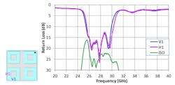
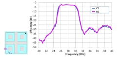
Figures 3 and 4 provide actual measurement results for the 2x2 antenna array with integrated BPFs. As shown in Figure 3, we achieve >10-dB return loss for individual horizontal and vertical polarization ports and >20-dB isolation between dual-polarized ports of individual antenna elements. This results in an average −3.5-dB efficiency of individual horizontal and vertical polarization ports (Fig. 4). The integrated solution clearly shows an overall BPF response with a steep slope out of the passband that can protect individual antenna channels to solve potential interference issues.
In mmWave beamforming antenna-array designs, installing series discrete BPFs to each individual antenna feeding port is challenged by the space constraints created by mounting beamforming ICs on the backside of the antenna arrays. The connections between discrete BPFs cause elevated insertion losses and phase shifts. On top of that, the individual antenna feeding ports can’t be ignored.
With its integrated BPFs, the antenna array described here could solve the space-constraint problem and provide the best integration performance. TDK consulted with multiple customers and obtained early system requirements to address all potential circumstances, and then applied this information to the design and optimization of the antenna array.
For the 2x2 antenna array with integrated BPFs solution in the 10.6- × 10.6- × 2.2-mm package, the result is a cost-effective approach for 5G infrastructure and consumer-premises-equipment (CPE) applications. Where larger arrays are needed, such as 8x8 or 16x16 configurations, the desired numbers of elements can be easily “tiled” up by integrating multiple 2x2 antenna arrays.
Conclusion
All industry marketing reports expect worldwide implementation of 5G mmWave systems to experience substantial growth over the next five to seven years. Concurrently, we suspect that adjacent mmWave-band interference will soon grow in severity as mmWave implementations ramp up. The key benefits of TDK’s LTCC antenna array with integrated BPFs include:
- Excellent antenna array with integrated BPF performance that can effectively reduce adjacent-band interference.
- High multi-layer design flexibility, convenient for matching different beamforming ICs.
- Cost-effectiveness and compact size, suitable for forming larger arrays by “tiling” multiple arrays.
- Precise process control and proven mature mass-production capability ensure performance and consistency of final products, meeting and/or exceeding customer requirements and being able to bring final products to the market in a timely manner.
Acknowledgement
The author thanks Harvey Espinoza and Chris Burket from TDK Corporation of America for helping review this article and the TDK Japan 5G team (Yasumasa Harihara and Tomoyuki Goi) for providing the antenna-array design and evaluation.
About the Author
Fang Liu
Product Marketing Engineer, TDK
Fang Liu is an RF product marketing engineer in TDK’s Communication Device Business Group, supporting RF and mmWave components in a variety of 5G applications. Fang is based in San Jose, Calif., and has over 15 years of industry experience in RF circuits and system design and manufacturing. He enjoys playing soccer with his son and collecting Transformers toys.
