Tiny MEMS Switches Route DC to 14 GHz
This file type includes high-resolution graphics and schematics when applicable.
Electromechanical switches and relays have been a part of RF/microwave circuits and systems design for some time. They can handle reasonable input power levels for their small sizes, but are typically slower and larger than solid-state switches.
Edging closer in speed to solid-state devices, a line of microelectromechanical-systems (MEMS) switches from Analog Devices targets RF/microwave signal switching in a fraction of the size and power consumption of electromechanical relays while promising considerably faster switching speeds and much greater reliability. The first two switches in the MEMS product line—single-pole, four-throw (SP4T) models ADGM1304 and ADGM1004—offer similar wideband performance from 0 Hz (dc) to 14 GHz, with the latter also incorporating electrostatic-discharge (ESD) protection.
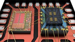
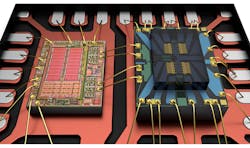
Analog Devices is no stranger to designing and fabricating MEMS devices, supplying MEMS accelerometers for airbags in motor vehicles since 1991.The two new RF/microwave switches, manufactured in the company’s own MEMS foundry, come in compact packages with silicon caps that provide hermeticity (Fig. 1). Each package includes an electrostatically activated MEMS switch die and a low-current, low-voltage driver IC (Fig. 2). The integrated driver is LVTTL/CMOS compatible for parallel interfaces; having the driver within the same miniature package as the MEMS chip simplifies circuit design and saves space on printed circuit boards (PCBs).
The two switches meet MIL-STD-883 requirements. Thus, they are well-suited for automatic-test-equipment (ATE) applications with high circuit density and in portable circuits and test applications where power is limited power (such as from a rechargeable battery).
The MEMS switches are not capacitive, but rather dc-coupled for a wide range of broadband applications. They are designed for use with nominal supply voltages of +3.1 to +3.3 V dc. The devices use spring force for actuation and de-actuation (Fig. 3), with very little wear on the contacts after an almost inconceivable number of switching cycles. In fact, both switches are rated for operating lifetimes of 1 billion minimum switching cycles. They are evaluated with the same reliability testing used by Analog Devices for its semiconductor devices to ensure consistency in lifetime testing. The two MEMS switches are capable of operating lifetimes that are 10× longer than typical electromechanical relays.
Switch Specs
In terms of performance, the model ADGM1004 SP4T MEMS switch has a 2.5-kV ESD rating per the human-body model (HBM); the ADGM1304 doesn’t include ESD protection. These miniature switches feature extremely low on-resistance of 1.8 â¦. Both are usable from 0 Hz (dc) to 14 GHz, with the ADGM1304 part having a typical insertion loss of 0.26 dB at 2.5 GHz and 0.4 dB at 6.0 GHz. The return loss is at least 13 dB at typically 18 dB from dc to 6 GHz. Isolation is customarily 24 dB at 2.5 GHz and 19 dB at 6.0 GHz, from the control to an RF output port. Crosstalk is typically 30 dB measured at 2.5 GHz.

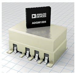
Although these are mechanical devices, they provide impressive switching speed, with 30 µs typical on switching time and 5 µs typical off switching time. The settling time for the rising edge of a switched signal is generally 40 µs and typically 8 µs for the falling edge. Both switches offer excellent linearity, with typical input third-order-intercept point (IIP3) of +69 dBm. The non-ESD-protected model ADGM1304, even with its compact size (Fig. 4), is rated for maximum input power to +36 dBm. It is quite capable of maintaining high signal integrity throughout its frequency range, with second harmonics of typically –90 dBc and third harmonics of typically –85 dBc.
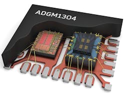
Model ADGM1004 and its ESD protection come in a 24-lead lead-frame chip-scale package (LFCP) measuring 5 × 4 ×1.45 mm, complete with LVTTL/CMOS driver. Model ADGM1304 is housed in a LFCP measuring 5 × 4 × 0.95 mm. Both switches are frugal on power consumption, consuming only 10 mW during normal operation.
These two switches are the first in what promises to be an extensive line of miniature high-speed MEMS switches for RF test instrumentation, automatic test equipment, and defense and aerospace applications. With their performance levels and operating lifetimes, these powerful new additions to Analog Devices' overall switch (SOI, GaAs, analog) offerings should provide a highly reliable solution for the targeted applications, enabling new system architectures and significant size reductions.
Analog Devices Inc., One Technology Way, P.O. Box 9106, Norwood, MA 02062-9106; (781) 329-4700

About the Author
Jack Browne
Technical Contributor
Jack Browne, Technical Contributor, has worked in technical publishing for over 30 years. He managed the content and production of three technical journals while at the American Institute of Physics, including Medical Physics and the Journal of Vacuum Science & Technology. He has been a Publisher and Editor for Penton Media, started the firm’s Wireless Symposium & Exhibition trade show in 1993, and currently serves as Technical Contributor for that company's Microwaves & RF magazine. Browne, who holds a BS in Mathematics from City College of New York and BA degrees in English and Philosophy from Fordham University, is a member of the IEEE.
