A Selected History of Receiver Innovations Over the Last 100 Years (Part 2)
One key point early radio pioneers like de Forest and Armstrong understood was that their successes were determined by a solid, reliable detector. In the early days, this was largely the wireless operator, whose technical and auditory skills made it possible. However, as the industry grew, other aspects became important, such as including linearity and bandwidth.
In 1912, to address these issues, de Forest figured out regeneration and how a receiver could benefit from this technique. At nearly the same time, Armstrong made similar discoveries, and he noted that if energy was coupled from the plate circuit back into the screen tuner, significant amplification occurred as the amplifier response peaked prior to free oscillation. These discoveries set off a multi-decade-long patent dispute as each inventor claimed his invention came first.
Regardless, the key advantage of the regenerative receiver was that, in addition to the very high levels of gain achieved, the receiver facilitated connecting the output to a speaker as opposed to the previous small headphone with a weak audio output. Armstrong noted that, with this arrangement, he could easily copy Marconi’s installation in Ireland from his New York lab, whereas Marconi typically required a relay station to achieve transatlantic coverage.
After he was satisfied with his results, Armstrong invited Sarnoff to his lab to share his discoveries. With his regenerative setup, they spent the night DXing and received signals from the West Coast and into the Pacific with ease. This was a major enhancement for detector technology.
The biggest challenge for the regenerative receivers was adjusting the feedback for proper operation—a challenging task even for an experienced operator. As early models of the regenerative and super-regenerative radios were put into production, this challenge became apparent and required resolution before radio technology could achieve widespread usage.
Superhet
World War I eventually drew the U.S. into the engagement and Armstrong received duty in France, where he was responsible for installing technology in the field. This afforded him the opportunity to continue his research, and in turn conceived of the superheterodyne architecture in February of 1918 after working with colleagues in both France and Britain. Eventually, this architecture resolved many of the tedious adjustments required in prior architectures like the super-regenerative type, without sacrificing performance.
Armstrong continued to develop the superheterodyne architecture throughout 1918, which solved many of the challenges of the regenerative and the super-regenerative receivers. This advance enabled easy-to-operate radios consistent with those in production today.
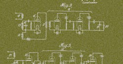
While a superheterodyne receiver is not strictly a detector, it does facilitate better, more consistent detection by including gain and additional selectivity, and by presenting a fixed IF regardless of the RF frequency being monitored. Thus, the detector can be optimized without concern of degradation as a function of the desired RF frequency. This was a huge challenge of early radio and continues to challenge radio designers today, albeit at much higher frequencies even as we continue to explore new architectures including zero-IF and direct-RF sampling (Fig. 1).
1. Superheterodyne patent figures.
These advantages have cemented the importance of heterodyne architectures—and this continues today. While the implementing technology has moved from tube to transistor to integrated circuit (IC), the architecture remains key to many modern systems.
ADCs, DSPs, and FPGAs
Outside of the shifting of technology types, little changed in radio architectures until the 1970s, with the advent of general-purpose digital-signal processors and field-programmable gate arrays (FPGAs). Detector functions moved from linear detector elements like diodes, discriminators, and phase-locked loops (PLLs) to analog-to-digital converters (ADCs) followed by digital signal processing (DSP). This enabled significantly more capability not possible with older technology.
While data converters followed by DSP can and do perform traditional AM and FM1 demodulation, use of digital-processing techniques enables complex digital demodulation used widely for digital television. This includes HD Radio in the U.S. and digital audio broadcasting (DAB) in Europe and other regions around the world.
In early digital systems, the IF stage was typically converted to a baseband signal with an I/Q demodulator and then digitized by dual low-frequency ADCs (Fig. 2). These early ADCs were relatively low bandwidth; therefore, radios tended to be narrowband systems. While these systems are workable for low-bandwidth systems, they suffered from quadrature mismatches that caused image rejection issues that had to be corrected by analog and later digital techniques.
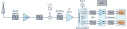
2. Dual-conversion baseband sampling.
Because early systems were not highly integrated, it was difficult to maintain balance between I/Q, which resulted in image errors (quadrature). This was complicated due to shifts over time and temperature that had to be carefully accounted for. Even in highly integrated systems, I/Q balance is typically limited to 40-dB or worse image rejection without some sort of corrective algorithm.
By the mid-1990s, converter technology began to improve enough that baseband I/Q sampling could be replaced with IF sampling (Fig. 3). This had several advantages. First, the demodulator and baseband converter pair could be eliminated and replaced with a single ADC, saving power and board space. More importantly, the errors associated with analog I/Q extraction could be eliminated. Of course, complex data was still required for DSP processing, but it could easily be extracted digitally by using digital downconverters (DDCs) like the AD6624 that provide perfect quadrature and do not drift over time or temperature.
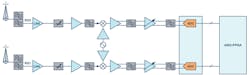
3. Typical IF-sampling architecture.
Initially, these IF sampling converters were narrowband. But in the late-1990s, wideband IF sampling converters became available, including devices like the AD9042 and AD6645. These new devices could sample IF frequencies as high as 200 MHz and provide a signal bandwidth of up to 35 MHz.
This technology became interesting enough that many high-performance receivers began adopting IF sampling to both simplify the radio and to improve performance. One of the many advantages of this technique is that one receiver signal path could process multiple RF carriers.2 This had the effect of allowing one radio to replace many analog narrowband radios and greatly reduce the cost of ownership in numerous telecommunications applications. Any application that processed multiple independent (or dependent) RF signals could benefit from this type of architecture, which allowed for a reduction in cost, size, and complexity.
Individual RF carriers are easily sorted out in the digital data stream where they could be independently processed as required. Each signal could be modulated differently with unique information or the signal bandwidth could be widened to increase the data throughput. Integrated mixer technology, including the ADRF6612 and ADRF6655, continues to move IF-sampling heterodyne radios forward by providing highly integrated and low-cost solutions when combined with new IF-sampling converters like the AD9684 and AD9694. These new ADCs include DDCs that not only digitally filter unneeded spectrum, but also digitally extract out the I/Q components.
Side by Side: Then and Now
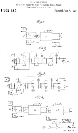
Armstrong’s patent3 states that “It is well known that all detectors rapidly lose their sensitiveness as the strength of the received signal is decreased, and that when the strength of the high frequency oscillation falls below a certain point, the response of a detector becomes so feeble that it is impossible to receive signals.” Armstrong claimed that as amplitude fell or as frequency increased, detector sensitivity was reduced. He and others sought a method to extend the usefulness of radio to higher frequencies and improve overall performance.
Based on earlier work with tubes such as the Audion tube and regeneration, Armstrong realized that he could convert the incoming frequency to one that worked more efficiently with the detectors available. Furthermore, gain could be applied to increase not only the RF signal level, but the audio signal level provided to the user.
Figure 4 shows one of the patent’s diagrams, which “illustrates in detail the utilization of [Armstrong’s] method using a tuned amplifier system wherein 21 is the source of the incoming oscillations (signals), and a vacuum tube rectifying system, 22, 23, 25, converts the combined oscillations of the incoming and those from the separate heterodyne 24 (local oscillator). The circuit, 26, 27, is tuned to the converted combination of the two oscillations (desired mixer product). A multi-tube high-frequency amplifier, 28, amplifies the resulting energy heterodyned and detected by the vacuum tube system, 29, and indicated by the telephones, 30.”
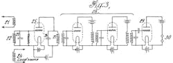
4. Armstrong’s superhet diagram.
By using this method, Armstrong was able to take the RF energy and shift the frequency to one that could easily and efficiently be detected, as well as provide sufficient amplification for a comfortable audio level. In his patent, he goes on to show that multiple stages of heterodyning can be applied, which has the advantage of providing additional selectivity and higher levels of gain without the concern of uncontrolled feedback causing oscillation—a problem that plagued earlier radio architectures such as the regenerative receiver.
The following figures help to better compare tube technology to a contemporary implementation. They also show how modern designs remain similar to the original design proposed 100 years ago.
Figure 5 shows both circuits placed side by side. The first tube stage, according to Armstrong’s patent, consists of a vacuum-tube rectifying system. This first stage combines the mixing of the desired signal with the LO by taking advantage of the rectifying properties of the tube to produce the typical mixing products.
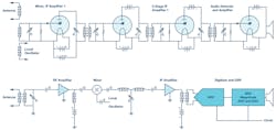
5. Tube vs. contemporary superhet.
Armstrong suggested 10 MHz (shown in Figure 6) as an RF because this was beyond what detectors of his time could respond to, and it represented a technical challenge to him during the period when he was developing the superheterodyne receiver. Modern receivers typically include at least one RF amplifier prior to the mixer to provide lower noise and better sensitivity, as is shown in the lower signal chain.
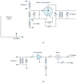
6. Tube front end (a), front end (b).
These devices are typically very low noise FET designs optimized for the frequency range of operation. The only fundamental difference between what Armstrong originally patented and modern designs is the separate RF amplifier placed before the mixer. By World War 2, it was common to find tube-type designs with front-end amplifiers equivalent to today’s FET front ends.
He suggested that this incoming RF signal could be combined with a local oscillator (LO) of perhaps 10.1 MHz to produce a new tone at 0.1 MHz during the first stage. We recognize this as the sum and difference products of a typical mixer (Fig. 7). In the tube schematic in Fig. 6, the LO was coupled directly into the input circuitry where the nonlinear behavior of the tube produced these products. One challenge this original design would have posed would have been unintended radiation of the LO by way of the direct coupling to the antenna. Contemporary designs are less susceptible to this radiation, although not completely, because, as shown in Fig. 7, the LO is coupled into a mixer isolated from the input by the front-end amplifier.
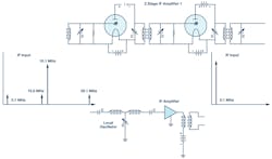
7. IF amplifier stage.
One improvement Armstrong proposed was that Amplifier 1 could also be used as the LO in addition to the detector by taking advantage of feedback from the plate into the grid circuit, similar to what he and de Forest accomplished with the regenerative receiver. This would have created a compact front-end function. In today’s circuitry, the mixer, LO, and RF and IF amplifiers are often included on a single IC. These devices are widely available for many different applications from consumer to industrial needs.
For both the tube and monolithic front ends, the mixing process produces sums and differences between the RF and LO. In Armstrong’s case, this meant 0.1 MHz and 20.1 MHz. In addition, it’s common to have both RF and LO leakage to the output as well. The unwanted terms created by the mixer must be filtered out to receive the desired signal. Since the bandwidth of the detector was limited, Armstrong focused in the difference term, 100 kHz. It’s likely that his two-stage IF amplifier provided some filtering of the other terms in addition to the resonant LC structures he included.
A contemporary IF amplifier will include some sort of IF filter as well. Fig. 7 shows a basic LC filter, but, often, some form of high-Q filter is utilized. Narrowband radios typically use quartz or ceramic filters for the IF stage; wider-band designs often take advantage of surface-acoustic-wave (SAW) or bulk-acoustic-wave (BAW) technology, depending on the requirements. This filter, often referred to as a roofing filter, is used to protect following stages from strong out-of-band signals.
With a well-filtered and strong IF signal, Armstrong could now easily detect what were once weak RF signals outside of the bandwidth of his detector. Now at an IF, they easily matched what detectors were capable of.
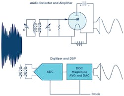
8. Detector.
In the case of the tube, these signals were rectified and then amplified so that they could drive a speaker directly, at least for amplitude modulated signals. In contemporary receivers, an ADC samples the analog IF and produces a digital equivalent, which is then processed digitally (including demodulation). In the case of an audio application, it can then be converted back to analog with a digital-to-analog converter (DAC) to drive a speaker if necessary (Fig. 8).
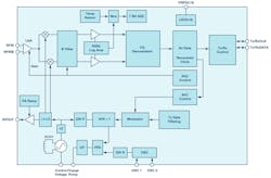
9. ADF7021 short-range wireless (simplified).
While both tube and transistor versions of these radios can achieve a similar result, contemporary designs have a range of advantages. Notably, modern designs are much smaller with greatly reduced power requirements. While portable tube radios existed from the beginning, transistors enabled pocket-size radios. ICs enabled single-chip radios for a wide range of applications from short-range wireless like the ADF7021 (Fig. 9) through high performance offered by way of AD9371 (Fig. 10). In many cases, this includes both the receiver and the transmitter.
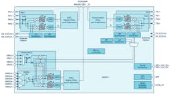
10. AD9371 ZIF transceiver.
Since monolithic radios typically utilize ADCs and DACs, these readily facilitate complex modulation. Tube-type radios historically were limited to basic modulation types, such as AM and FM. When data converters are added to the radio, as is typically done on monolithic radios, new forms of modulation can be introduced by way of digital techniques, including spread spectrum and OFDM, which are at the heart of most modern communications (digital TV, HD Radio, DAB, cell phones) that we rely on daily.
As radio technology continues to evolve, more advances will come that may enable radio architectures or provide functions not currently possible. Today, we have a wide selection of IF-sampling superheterodyne and zero-IF architectures in highly integrated forms. Other architectures on the horizon include direct-RF sampling in which the signal is directly converted to digital without analog downconversion. As radio technology continues to evolve, the number of available options will grow. However, it’s likely that some form of heterodyne will be with us for some time to come.
Conclusion
In the 100 years of the superheterodyne radio, little has changed in the architecture except the implementation technology. We have witnessed many changes through the years in terms of the medium on which radios have been constructed, with technology migrating from tubes to transistors to monolithic ICs. These changes have enabled possibilities that were only a daydream to the early radio pioneers and now our daily lives are so closely tied to.
One of the key elements that has made this possible is the detector fulfilled by the high-speed ADC in today’s radio technology. Improvements over the last few years in data-converter and other technology has ushered in our connected world, which is changing our daily lives and the fabric of modern society. The exciting part is that this core technology is continuing to evolve, which will continue to enable new, perhaps unknown, wireless solutions. The next 100 years carry as much potential to the next generation of wireless as Armstrong and Levy’s inventions provided to the last 100 years.
References:
- Fred Harris. “Exact FM Detection of Complex Time Series.” Electrical and Computer Engineering Department, San Diego State University.
- Walter Tuttlebee. Software-Defined Radio: Enabling Technologies, Chapter 4: Data Conversion in Software Defined Radios. Wiley, 2002.
- Edward H. Armstrong. U.S. patent 1342885, “Method of Receiving High Frequency Oscillations.” Application filed February 8, 1919, issued June 8, 1920.

About the Author
Brad Brannon
System Applications Engineering Director, Analog Devices Inc.
In his 37-year career at Analog Devices since graduating from North Carolina State University, Brad Brannon has held positions in design, test, applications, and system engineering. Currently, Brannon develops reference designs for O-RAN in support of those customers. He has authored several articles and application notes on topics that span clocking data converters, designing radios, and testing ADCs.
