RF Energy Development in a Box
A great deal of interest surrounds RF energy applications, with various companies leading the charge in that arena. One such firm is NXP Semiconductors, which recently unveiled its RFE Series of system solutions for RF energy applications. This RF energy platform offers performance at 2.45 GHz and can deliver 250 W of RF power.
NXP maintains that “the enhanced control features and reliability that solid-state technology brings to systems using RF energy have long been understood. However, RF power transistors lacked development tools to help engineers leverage them.” This is where the RFE Series steps in—the platform delivers new ways to prototype and develop high-performance systems.
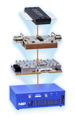
1. Shown from top to bottom: the MRF24300N RF power transistor, the RFEP24-300 pallet, the RFEM24-250 module, and the RFEL24-500 lab box.
The RFE Series consists of the RF energy lab box (RFEL24-500), RF energy module (RFEM24-250), RF energy pallet (RFEP24-300), and the MRF24300N RF power transistor. Figure 1 shows all four of these elements in a top-to-bottom representation, starting with the power transistor. This multi-level portfolio is intended to address all levels of expertise, according to NXP.
Breaking Down the RFE Series
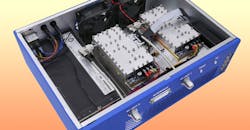
The RFEL24-500 lab box covers a frequency range of 2,400 to 2,500 MHz (Fig. 2). It has two channels that can each deliver 250 W of continuous-wave (CW) power. The box includes two RFEM24-250 modules along with fans, a power supply unit, and a heatsink. It also features a USB interface. The 13- × 17- × 5-in. lab box is designed for evaluation and initial prototyping—no RF expertise or RF equipment is required.
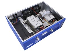
2. The RFEL24-500 lab box contains two RFEM24-250 modules plus other integral series devices.
A PC-based graphical user interface (GUI) is a significant aspect of the RFEL24-500 lab box (Fig. 3). The software lets users control power, frequency, and phase. Power and phase can be controlled for each module separately; frequency is controlled for both modules simultaneously (i.e., dual-module frequency control). Furthermore, four measurements per module are displayed: forward power, reverse power, temperature, and current.
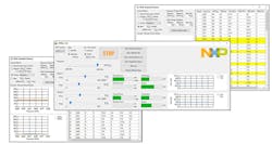
3. The lab box software lets users control power, frequency, and phase, as well as view various measurements.
Another dimension of the software is its Extended Features section, which allows for frequency and phase sweeps. Once complete, the software can automatically select the frequency/phase combinations that enable the highest transfer of energy (forward power − reflected power).
The RFEM24-250 module delivers 250 W from 2,400 to 2,500 MHz. It requires a supply voltage ranging from 24 to 32 V, as well as 5-V control voltage. Figure 4 shows a block diagram of the RFEM24-250, revealing three amplifier stages, an integrated RF source, an I2C communications interface, and more. The MRF24300N power transistor is used for the final amplifier stage.
4. Key to the RFEM24-250 module is its three amplifier stages.
In addition, the RFEM24-250, which measures 3 × 4 × 1 in., includes sensing for forward power, reflected power, current, voltage, and temperature. As many as four modules can be combined and synchronized.
The RFEP24-300 pallet provides 290 W of CW power from 2,400 to 2,500 MHz. It’s a three-stage reference design that’s intended to “jump-start power-amplifier (PA) development,” according to NXP. The MMG20271H9 monolithic microwave integrated-circuit (MMIC) amplifier serves as the pre-driver, while the MHT1008N RF power transistor is utilized for the driver stage. The MRF24300N transistor is used for the final amplifier stage. Overall, the complete lineup provides over 41 dB of gain. The pallet measures 2 × 3 in.
The MRF24300N transistor itself delivers 300 W of CW power from 2,400 to 2,500 MHz. It provides 13 dB of gain and achieves a drain efficiency of 60%. The device is known for its ruggedness—it can withstand a voltage standing wave ratio (VSWR) as high as 5:1.
Bringing Everything Together
So, how can customers take advantage of these multiple solutions? The first option is to use the RFEL24-500 lab box for evaluation of solid-state RF energy and initial prototyping. NXP recommends to start with the lab box, which is essentially a turnkey solution.
Another option involves the RFEM24-250 module to create a proof of concept (PoC). Customers would combine the module with their own power supplies, cooling system, control logic, and software. An NXP-recommend third-party would then tailor the module to meet the customer’s specific needs to create a cost-effective, high-volume manufacturable solution.
Customers could also start with the RFEP24-300 pallet and then work with NXP-recommended third-party RF PA and/or electromagnetic antenna/cavity design houses to build a solution. Alternatively, they could invest in moderate RF lab equipment and expertise and then copy the reference design. Lastly, a customer could choose to start with the MRF24300N transistor and work with a contract manufacturer.

