Need More Bandwidth for the Ka-Band? Here Are Three Options

Download this article as a .PDF
As the demand for global connectedness increases, many satellite communications (satcom) systems are pushing toward higher data rates with an increased presence in the Ka-band spectrum. With high-performance signal chains now able to support multiple GHz of instantaneous bandwidth, and with potentially hundreds of transceivers in a system, the potential for very-high-throughput data rates is now a reality.
In addition, there is a trend in many systems to move away from static mechanically-steered parabolic antennas and move toward active phased-array antennas. This is driven by the enhanced technology and increased integration available to drive element spacing down to what is required at Ka-band frequencies. Phased-array technology also allows for improved interference mitigation by creating nulls in the antenna pattern in the direction of interfering signals.
The following overview describes some of the tradeoffs that exist among the transceiver architectures available, as well as what types of architectures may be appropriate for different types of systems. Included in this analysis is a breakdown of some of the key specifications for a satellite system and how these system-level specifications translate to transceiver signal-chain-level components.
Specification Flow-Down from System-Level Analysis
Satcom systems at a high level are concerned with maintaining a certain carrier-to-noise ratio (CNR), which is a result of the link-budget calculation. Maintaining this CNR ensures a certain bit-error-rate (BER). The CNR required depends on many factors, such as error correction, information coding, bandwidth, and modulation type.
Once a required CNR is established, the individual receiver and transmitter specifications can flow down from the high-level system requirements. Typically, they will first flow down in the form of a required gain-to-system-noise-temperature (G/T) figure of merit for receivers, and effective isotropic radiated power (EIRP) for transmitters.
For the receiver, translating from G/T to a lower-level receiver signal-chain specification requires the system designer to know the antenna gain and system noise temperature, as shown in Eq. 1 below. The receiver noise temperature can be determined from Eq. 2.


The noise figure required of the receiver signal chain can then be found from Eq. 3:

Once the receiver noise figure is known, a cascade analysis can be computed to determine if the signal chain is meeting these required specifications and if adjustments can be made as necessary.
For the transmitter, the EIRP needed is first determined based on how far away the receiver is (either ground-to-satellite or satellite-to-ground) and how sensitive the receiver is. Once the EIRP requirement is known, a tradeoff exists between the output power of the transmit signal chain and the gain of the antenna. With a higher-gain antenna, the power consumption and size of the transmitter can go down but at the expense of a larger antenna. The EIRP is given by Eq. 4.

Carefully selecting components in the signal chain allows the required output power to be maintained without causing degradation to other important parameters. Such parameters include output noise spectral density and out-of-band RF energy that can cause interference in other systems.
Other critical specifications for both the transmitter and receiver include:
Instantaneous bandwidth. How much spectrum the signal chain can digitize at any point in time.
Power handling. How large of a signal can a signal chain handle without degrading performance.
Phase coherency among channels. For emerging beamforming systems, ensuring predictable phase between channels to allow for simplified beamforming signal processing and calibration.
Spurious performance. Ensuring the receiver and transmitter do not produce RF energy at undesired frequencies that can impact the system or other system’s performance.
Keeping these specifications and others in mind when designing a signal chain is critical to guarantee a high-performance system for any given application, whether a wideband multi-carrier-aggregation hub or an individual narrowband handheld satcom terminal.
General Architecture Comparison
Once the high-level specifications are determined, the signal-chain architecture can be decided upon. One of the critical specifications previously listed that can have a big impact on the architecture is instantaneous bandwidth. This impacts the analog-to-digital converter (ADC) for the receiver and digital-to-analog converter (DAC) for the transmitter. To achieve greater instantaneous bandwidth, the digitizers must be sampled at a higher rate, which can generally drive up power consumption of the signal chain as a whole, but decrease power consumption if judged on a W/GHz basis.
For systems with less than 100-MHz bandwidth, a base architecture that is similar to the one shown in Fig. 1a is optimal in many cases. This architecture utilizes a hybrid approach, as it pairs a standard downconversion stage with an integrated direct-conversion transceiver chip. The integrated transceiver provides a high level of integration, drastically reducing size and power.
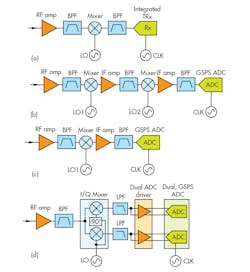
1. This figure shows four different architectures: High-IF with integrated TRx (a), dual-conversion superheterodyne with GSPS ADC (b), single-conversion superheterodyne with GSPS ADC (c), direct-conversion with I/Q mixer (d).
To achieve as much as 1.5 GHz of bandwidth, one can utilize a classic dual-conversion superheterodyne architecture in conjunction with the latest ADC technology (Fig. 1b). With this well-established, high-performance architecture, conversion stages are used to filter out unwanted spurious signals. Depending on the receive frequency band, the first downconversion stage is utilized to downconvert to an intermediate frequency (IF).
Following the first downconversion stage, an additional downconversion stage is utilized to downconvert to a lower-frequency final IF that the ADC can digitize. The lower this final IF, the higher the ADC performance will be but at the expense of increased filtering requirements. Generally, due to the increased component count, this architecture is the largest and highest-power version of the four options presented.
Another similar option involves converting to a higher IF with a single-conversion stage followed by sampling using a gigasample-per-second (GSPS) ADC (Fig. 1c). This architecture takes advantage of the increasing amounts of RF bandwidth that ADCs are able to digitize with very little performance degradation. The latest GSPS ADCs on the market allow for direct sampling of RF frequencies as high as 9 GHz. In this option, the IF is centered somewhere in the range of 4 to 5 GHz to strike the best balance between filtering requirements for the signal chain and ADC requirements.
Figure 1d shows the final option. This direct-conversion architecture provides even greater instantaneous bandwidth, but comes at the expense of complexity and potentially decreased performance. This architecture uses a passive in-phase/quadrature (I/Q) mixer, allowing for two IFs at baseband that are 90 deg. offset from one another.
Each I and Q leg is then digitized using a dual-channel, GSPS ADC. In this case, as much as 3 GHz of instantaneous bandwidth is possible. The major challenge associated with this option is maintaining the quadrature balance between the I and Q paths, as the errors propagate through the mixer, low-pass filter, and ADC driver. This may be an acceptable tradeoff, depending on CNR requirements.
A general overview has been given here that describes, at a high level, the operation of these receiver architectures. The architectures presented here are not all inclusive by any means, as hybrids that use elements of each option are also possible. Although transmit signal chains were not covered in the comparison, each option from Fig. 1 has a corresponding transmit signal chain with similar tradeoffs.
Ka-Band Satcom Receiver Examples
Now that the pros and cons of different architectures have been discussed, the knowledge can be applied to real signal-chain examples. Many satcom systems are now operating in the Ka-band in order to decrease antenna size and increase data rates. This is especially relevant in high-throughput satellite systems. The following is a discussion of examples using different architectures along with a more detailed comparison.
2. This architecture utilizes a high-IF and has an integrated TRx. It allows for bandwidth up to 100 MHz.
For systems that require instantaneous bandwidth below 100 MHz, such as is the case with very small aperture terminals (VSATs), the high-IF architecture with an integrated transceiver chip (AD9371) can be used (Fig. 2). This design can achieve low noise figure, and because it has such a high level of integration, it offers the smallest design footprint. A summary of its performance can be seen in the table.
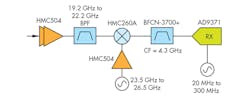
Some systems may be dealing with many carrier signals at a time if they are acting as a hub for multiple users in a satcom system. In this case, bandwidth per receiver or bandwidth/power become important factors. Figure 3 shows a signal chain that utilizes a high-speed ADC. The ADC used here is the recently released AD9208, which is a high-sample rate ADC that can digitize as much as 1.5 GHz of instantaneous bandwidth. In this example, the IF is placed at 4.5 GHz to achieve 1 GHz of instantaneous bandwidth. The achievable bandwidth here will depend on filtering requirements for the anti-alias filter before the ADC, but is generally limited to approximately 75% of a Nyquist zone (half of the sample rate).
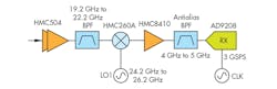
3. This figure depicts a single-conversion-to-high-IF architecture that utilizes the AD9208 ADC.
In systems that demand the highest instantaneous bandwidth and can give up performance in the form of CNR, the direct-conversion signal chain shown in Fig. 4 may be desirable. This signal chain utilizes an I/Q mixer, the HMC8191, which has an image rejection performance of approximately 25 dBc. In this case, the image rejection is limited by the amplitude and phase balance between the I and Q output channels. This is the limiting factor for this signal chain without more advanced quadrature-error-correction (QEC) techniques.
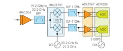
4. Shown is an example of a direct-conversion architecture that includes an I/Q mixer and GSPS ADC.
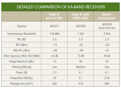
A summary of the direct-conversion signal-chain performance is shown in the table. Notably, the noise figure and third-order intercept (IP3) performance is similar to the other options, but the power/GHz metric is the lowest of the three. Size is similarly optimal for the amount of bandwidth that can be utilized at any instant.
While the three receive options presented here are shown in the table, it should be noted that this list is not meant as a comprehensive breakdown of all possible options. This summary overview is given in order to show differentiation among the various signal chain options. In any given system, the final optimal signal chain may be one of the three shown or a hybrid approach of any of these.
Additionally, even though only the breakdown for the receiver side is shown, many similar tradeoffs exist for transmitter signal chains as well. Generally, there is a tradeoff between the bandwidth and performance as systems move from a superheterodyne-based architecture to a direct-conversion-based architecture.
Data Interface
Once the data has been digitized by the ADC or transceiver, it must be passed along through a digital interface to be processed by the system. All of the digitizers mentioned utilize the high-speed JESD204B standard, which takes the bits from the data converter and packages them into frames to be transmitted on a small number of traces. The data rate coming out of the chips will vary based on system requirements, but all of the mentioned parts have digital functionality to decimate and frequency shift to accommodate various data rates to suit different system requirements.
This specification allows for up to 12.5 GSPS speeds on the JESD204B lanes, which is fully taken advantage of for high-bandwidth systems passing large amounts of data. Detailed descriptions of these interfaces can be found in the datasheets for the AD9208 and AD9371. Furthermore, selection of the FPGA must take into account this interface. Many FPGAs from vendors such as Xilinx, Altera, and others now incorporate this standard into their part for easy integration with these data converters.
Conclusion
The analysis shown has broken down the various tradeoffs and given specific examples of signal chains appropriate for satcom systems operating in the Ka-band. Among the several options presented is a single-conversion-to-high-IF architecture that utilizes the AD9371 integrated transceiver. A similar architecture uses a GSPS ADC in place of the integrated transceiver to increase instantaneous bandwidth. Additionally, a direct-conversion architecture increases bandwidth, but comes at the expense of decreased image rejection.
Although the signal chains presented can be used directly, they are intended to be starting points in the design process. Depending on the system-level application, different requirements will emerge, and a clear path will likely be evident that will favor one signal chain over the other.
References
- Bosworth, Duncan and Wyatt Taylor. “Bandwidth Demands Place New Strains on Satellite Communications Design.” Analog Devices, Inc., 2016.
- Delos, Peter. “A Review of Wideband Receiver Architectures.” Analog Devices, Inc., 2017.
- Hall, Brad and Wyatt Taylor. “Small Form Factor SATCOM Solutions.” Analog Devices, Inc., 2017.
- Bousquet, Michel and Gerard Maral. Satellite Communications Systems—5th West Sussex: John Wiley & Sons, Inc., 2009.

