Download this article in PDF format.
Radio signals are part of many wireless-communications applications, from consumer and commercial through industrial and military systems. Whether in licensed or unlicensed applications, especially at RF and lower-microwave frequency bands, any operating environment can become tangled with too many signals. Some of them are signals intended for a receiver, others are intended but too much for a receiver to handle at one time, and some are simply unwanted signals or interference.
Those unwanted signals can start from many sources, whether they’re as familiar as an AM radio or television broadcast transmitter and or in the form of harmonics of intended signals or even excessive energy leaking from electronic devices as electromagnetic interference (EMI). Typically, unwanted signal interference starts with some form of transmitter or as electronic equipment lacking adequate shielding to maintain electromagnetic compatibility (EMC) for a given operating environment. By knowing a little more about these unwanted signals, they can be sidestepped by the desired signals or filtered out when they occur at some point outside of the frequency bands of intended signals.
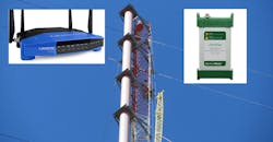
Organizations such as the Federal Communications Commission (FCC) and the International Telecommunication Union (ITU), and even the Amateur Radio Relay League (ARRL), work hard to organize frequency-spectrum use into carefully organized and managed bands of frequencies for each application. This includes, for example, the 2.4- to 2.5-GHz band for Wi-Fi wireless local-area networks (WLANs) and their essential wireless access to the internet for many different electronic devices. Starting within the kilohertz range for AM radios through VHF/UHF broadcast television channels (Fig. 1), spectrum use is carefully monitored to prevent unwanted overlapping of signals that can interfere with the reception of designed signals.
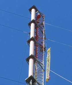
1. Radio broadcast antennas can be a starting point for radio waves that become unwanted interference signals. (Courtesy of Beckman Tower)
The 2.4-GHz span is part of the unlicensed industrial, scientific, and medical (ISM) band of frequencies intended for widespread and easy-to-use wireless applications. One of those applications, though, is the microwave oven at 2.45 GHz, where such relatively long wavelengths are effective for heating water and any foods or materials with water content. As effective as microwave ovens are for home and industrial heating, they are also a potential source of EMI and unwanted signals if improperly shielded and sealed during the heating process.
Wreaking Havoc on Wi-Fi
Although microwave ovens are designed to operate with relatively low levels of RF radiation, small amounts of leaking RF energy are enough to jam or interfere with the operation of nearby Wi-Fi equipment and prevent wireless access. Interference within the 2.4-GHz band may not be enough to prevent a Wi-Fi system from operating altogether, but may surface as slow internet access speeds and slow computer file transfers using the Wi-Fi system. For a Bluetooth device at 2.4 GHz, interference may result in simply not being able to wirelessly connect a Bluetooth device, such as a printer or computer mouse, to a computer controller.
Interference can also occur within Wi-Fi bands (at both 2.4 and 5 GHz) simply because of signal congestion. Interference results between fixed in-home wireless networks when a close-enough neighbor has set a wireless router to the same channel at the same frequency as the Wi-Fi system next door. Since Wi-Fi operates over a designated frequency bandwidth with multiple channels each set to its own frequency, changing the channel number will usually avoid interference in a Wi-Fi system from a too-near Wi-Fi wireless router (Fig. 2).
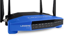
2. Standard Wi-Fi routers operating at ISM frequencies can be the sources—and victims—of unwanted interference signals. (Courtesy of Linksys)
Interference occurs when attempts are made to use multiple signals within the same frequency channel at the same time without some form of synchronization. Such instances may involve frequency-division multiplexing (FDM) to slightly offset the frequencies of the different signals or time-division multiplexing (TDM) when signals are transmitted in pulses or packets that are slightly offset in time to prevent the signals from blocking each other.
Of course, even the most dedicated attempts at signal synchronization cannot avoid interference in all cases. For example, in the case of a Wi-Fi system that may be initiating operation from a cable-television (CATV) service provider, coaxial cables running into a house and to a junction box can also be the source of interference. Frayed or cut insulation on those cables, even coaxial connectors with poor EMC interfaces, can leak enough EM energy into the operating environment to jam the intended RF signals from the wireless router to a nearby wireless device and degrade the overall performance of the Wi-Fi network.
In some wireless transmit systems, it’s also possible that out-of-band signals generated by second or third harmonics from internal power amplifiers for the transmitter may be emitted by the system at sufficient power levels to become interference for higher-frequency bands. Harmonics can occur for any transmitted frequency band that must be amplified, simply as the result of all amplifiers being guilty of some amounts of harmonic distortion. Systems with known harmonic levels will usually integrate bandpass filters (BPFs) that have enough bandwidth and low-enough passband loss to allow desired signals to pass through the system and adequate out-of-band signal rejection to prevent the transmission of those unwanted, higher-frequency signals.
Licensing Spectrum
In contrast to unlicensed ISM band frequencies, frequency bands licensed by the FCC, such as the cellular radio bands at 824 to 849 MHz and 869 to 894 MHz, are organized into what became 25-MHz channel blocks for different cellular carriers. The intention was to maintain effectively spaced signals that would provide multiple users within the same channel block and same locale with minimal or no interference from unwanted signals, such as radiating harmonics from lower-frequency emitters that might occur within a cellular channel at the same time as an intended transmission. Similarly, the FCC licensed higher-frequency spectrum at 1850 to 1990 for cellular communications use, in what became known as the personal communications service (PCS) band. The frequency range was divided into blocks between 10 to 30 MHz for wireless communications in different geographic areas of the U.S., as a means of preventing signal overlap and interference.
Receivers designed for a single frequency at a time can only process one signal at a time from a single transmitter. Such wireless circuits are often used in remote-control applications or as keyless-entry systems in automobiles. When more than one signal is transmitted at the same frequency and at the same time, the signals will jam and interfere with each other, and the receiver will fail to receive either signal because of the interference.
When an application requires that multiple signals be transmitted and received within the same frequency, some form of TDM arrangement is often applied to prevent the short bursts of signals at the same frequency from transmitting at the same time. By offsetting multiple signals even by short durations, interference from unwanted signals can be avoided and the multiple signals are able to share the same frequency or even a narrow-bandwidth frequency channel.
Identifying Interference
How does one locate unwanted signals within an operating environment? One of the best tools is a portable spectrum analyzer (Fig. 3), available from several high-frequency instrument suppliers (see, for example, "Instruments Bring the Value to Precision Measurements") and covering many different frequency ranges, through millimeter-wave (mmWave) frequencies. An analyzer with sufficient measurement bandwidth, when used with an antenna that covers the frequency range of interest and is as low in frequency as possible (to look for fundamental-frequency sources of harmonic signals that may be falling into the desired frequency band), can be used to measure the power levels of RF/microwave signals present in that operating environment. It also will likely display those signals along with a desired signal to compare the frequency congestion and power levels of the different signals.
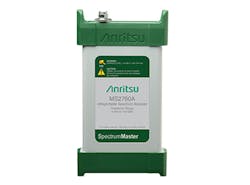
3. Modern, portable spectrum analyzers such as this model MS2760A from Anritsu provide spectrum monitoring in handheld sizes to help find unwanted interference signals. (Courtesy of Anritsu)
In addition, the portability of the analyzer and antenna may make it possible to move the measurement rig in different directions to identify when the signal levels of the interference increase. This helps locate the source of the unwanted, interfering signals, especially if within a home or an office.
As frequency spectrum use moves higher in frequency, into the millimeter-wave (mmWave) bands from 30 to 300 GHz, the intention by the FCC and other frequency-management organizations is to prevent interference as much as possible. Although the mmWave frequency range is currently uncongested, the same was once true at many RF and microwave frequency bands, such as 2.4 to 2.5 GHz.
These higher-frequency mmWave signals, whether for emerging applications like 5G cellular communications or automated driver-assistance systems (ADAS) for future autonomous driverless vehicles, are subject to many of the same traits as lower-frequency signals. Such mmWave signals can result in interference and generation of unwanted signals if improperly managed. In ADAS systems, of course, unwanted signals such as second harmonics of 30-GHz signals can generate 60-GHz signals that may cause traffic safety problems.

About the Author
Jack Browne
Technical Contributor
Jack Browne, Technical Contributor, has worked in technical publishing for over 30 years. He managed the content and production of three technical journals while at the American Institute of Physics, including Medical Physics and the Journal of Vacuum Science & Technology. He has been a Publisher and Editor for Penton Media, started the firm’s Wireless Symposium & Exhibition trade show in 1993, and currently serves as Technical Contributor for that company's Microwaves & RF magazine. Browne, who holds a BS in Mathematics from City College of New York and BA degrees in English and Philosophy from Fordham University, is a member of the IEEE.
