Download this article in PDF format.
Antennas are RF/microwave components that lend themselves to 3D printing, especially with the large volumes, miniaturization, and repeatability required for antennas in many mobile applications. Certainly, design engineers have considered the possibility of printing different types of miniature RF/microwave antennas. However, they may have wondered about how the performance of these printed antennas might compare to traditionally manufactured antennas.
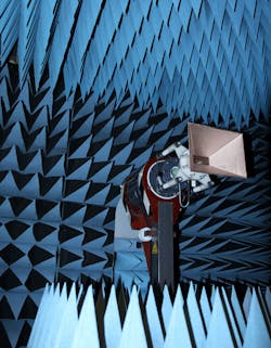
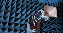
1. This anechoic chamber was used to isolate and test the 3D-printed antennas to 40 GHz.
To help RF/microwave engineers better understand the capabilities of antennas produced by 3D printing, Antenna Test Lab Company modeled printed, metallized, and tested a family of 15-dBi standard-gain horns for use from 2 to 40 GHz. The company is a professional antenna test laboratory with anechoic chamber (Fig. 1) to isolate antennas under test from outside RF/microwave energy sources and signals.
Some trial-and-error is involved in the process of producing and characterizing these antennas, especially over such a wide frequency range, but the benefits of 3D printing can be dramatic. For example, commercially available standard gain horns are typically quite expensive, with price tags ranging from $500 to $1500 depending on frequency range. Once the expense of learning how to print RF/microwave antennas has passed, compare those prices to the cost of producing a 3D standard gain horn at microwave frequencies for about $1.
The 2- to 40-GHz frequency range was chosen for antenna testing to encompass the practical limits of current 3D-printing technology. At S-band frequencies (2 to 4 GHz), a 15-dBi standard gain horn is about the size of a salad bowl and requires the use of a large-format printer to produce. It can also be printed in sections; the sections are combined to form a larger antenna. Since this S-band frequency range includes Wi-Fi, it should have a great deal of appeal for experimenters despite the antenna’s large size.
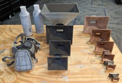
2. A variety of different antenna types and sizes can be formed by 3D-printing plastic foundations that are subsequently coated with conductive paints.
At Ka-band frequencies (26 to 40 GHz), the smaller wavelengths will result in a much smaller antenna—the same 15-dBi standard gain horn will fit into the palm of the hand (Fig. 2). The smaller dimensions of the antenna will also challenge the tolerance capabilities of typical 3D printers. Since test equipment, such as signal generators and vector network analyzers (VNAs), can be quite expensive for use above 40 GHz, these 3D antenna experiments were limited to a top frequency of 40 GHz.
For metallization, shielding spray paints from MG Chemicals were selected for their ease of use and ready availability (even online from Amazon). The first test antenna was an X-band horn (8 to 12 GHz) with an easy-to-print 4-in. aperture. Two copies of the antenna were printed to evaluate two common shielding spray paints: “841 Super Shield Nickel” and “843AR Super Shield Silver Coated Copper.” Each copy of the antenna was given two coats of the shielding spray paint, with suitable drying time between coats.
Datasheets for both shielding spray paints indicated impressive values for surface conductivities, and the resulting metallized horns provided attractive surface appearances (left side of Fig. 3). Unfortunately, appearances can be deceiving, as was revealed by the resulting measurements from within the anechoic chamber. The forward gain for these X-band horns was only about 5 dBi, or about 10 dB less than the expected level of 15 dBi.
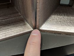
3. The antenna surface roughness resulting from 3D printing must be smoothed by sanding or via solvents to achieve low-loss performance at high frequencies.
Still, measurements showed that both antennas provided respectable directivity of about 15 dB with the expected beam widths of 30 deg. The return loss was considered good, at better than 20 dB. This combination of some good performance parameters with poor gain was considered a result of poor surface conductivity for the metallization treatment, causing the horns to suffer about 10 dB of loss from the expected gain.
A simple bench test was devised to prove this theory and to “pretest” antennas for this kind of loss. The method does not require an antenna test laboratory or even an anechoic chamber and can be quite useful for anyone working with antennas. The evaluation method involves measuring the return loss (VSWR) of an antenna as a quick pretest characterization.
As a rule of thumb, an antenna with high return loss, or more than 10 dB, is considered a good antenna. This evaluation is based on the thinking that, for a return loss of 10 dB, 90% or more of the transmitted energy sent to the antenna will radiate from the antenna since it’s not reflected to the energy source. Such a test of return loss or VSWR is normally useful, when an antenna can be assumed to have low losses. However, even lossy antennas or dummy loads are capable of excellent return loss.
A short circuit will yield low return loss. When a coaxial cable or the aperture of a low-loss metal horn antenna is short-circuited, low return loss (large reflections) can be expected. Such low return-loss behavior was verified for “shorted” laboratory-grade commercial horn antennas by covering their apertures with aluminum foil used for baking and cooking. The same shorted aperture test on the 3D-printed horn antennas showed large (greater than 20 dB) return loss, indicating that they were functioning better as attenuators than as antennas.
Figure 4 shows how an antenna with a “smoothed” surface exhibits low return loss. While there’s some ripple due to the unevenness of the cooking foil short circuit on the horn, the important behavior is the low return loss (about 1 dB) at some frequencies. This could not happen if the inside surfaces of the antenna were lossy.
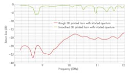
4. These plots of return loss through 12 GHz show the difference for 3D-printed surfaces that have been unaltered versus antenna surfaces that have been smoothed.
Despite the shiny appearance of the metallized paint, and the near-zero measured ohmmeter resistance readings of the applied metallized surface, the suspected loss mechanism was the surface resistance of the metallized finish. The tiny surface ripple artifacts of the 3D-printing layers are small compared to the relatively large operating wavelength (1 in. at X-band frequencies). However, surface smoothing did eventually prove to be the key to removing this loss and achieving the target 15-dBi gain across the full 2- to 40-GHz target frequency range for the printed antennas. But even applying multiple “liberal” coats of conductive paint did not sufficiently lower this loss without prior smoothing.
Smooth Operator
Smoothing the plastic surfaces of a 3D-printed antenna is a necessary step in achieving the target gain performance from those surfaces once they are metallized. Sanding is one way to smooth the 3D layer surface roughness, but it’s time-consuming. The funnel shape of the horn also results in triangular facets that are enclosed and tapered, forming a surface that’s not practical for power sanding tools to work on.
After experimentation, it was found that “solvent smoothing” required the least time and effort with satisfactory results. Acetone is a useful and well-known solvent for ABS plastic prints, and it worked well with prints from a smaller ABS filament printer. The large-format printer uses only PLA filament, for which there does not seem to be a readily available solvent. Some research did reveal that dichloromethane (methylene chloride) was a candidate solvent for PLA plastic, and was found to be highly effective at softening and smoothing the plastic’s surface roughness.
Both acetone and dichloromethane solvents are hazardous, but dichloromethane is especially poisonous. Though historically the key ingredient in common paint-stripper products, it’s being phased out due to its toxicity when used for do-it-yourself (DIY) home projects. After some trial-and-error, the following process was found to work quite well. The smoothed surface of the 3D-printed antenna that resulted from this process is shown on the right-hand side of Fig. 3.
For those inclined to work on their own 3D-printed antennas, the smoothing process should be performed outdoors, since it’s typically not possible to achieve adequate ventilation to be safe indoors. A respirator mask will still be needed when working outdoors (Fig. 4, again). The mask should be rated for organic solvents (commonly available for use with oil-based paints). It’s important to use full-length chemical gloves that are specifically rated for the type of solvent used. Such delicate chemical gloves should be protected by also wearing work gloves on top of them. Eye protection should also be worn during this chemical smoothing process, since it can be difficult to control where solvent lands in the workplace.
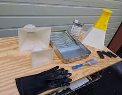
5. These are the tools for smoothing a 3D-printed antenna surface outdoors.
For convenience, solvent was poured into a standard metal paint-roller tray from which it could be applied to the 3D-printed antennas (Fig. 5). Common kitchen utensils such as disposable bristle brushes and metal pot-scrubbing pads were used in the application of solvent. Dichloromethane should not be handled with plastic brushes of any kind, since it will soften the material. It takes only a minute to smooth the inside of even the largest horn with the pot scrubber (or steel wool) if it’s kept wet with solvent. A round bottle brush worked well in scrubbing the waveguide portion of the horn. The outside of the horn was not smoothed or metallized; just the inside surfaces and mating flange.
For those attempting to assemble a larger antenna from smaller component parts, the process involving application of the solvent is also a good time to perform a “solvent weld,” since the plastic parts will already be softened by the solvent. The plastic welds can be achieved by pressing and holding together the parts to be joined for about 1 min. while the solvent evaporates.
Applying the conductive spray paint to the surface of the 3D-printed antennas is straightforward, as is done with any form of spray painting. For safety, it’s best done outdoors, with care to completely coat all inside surfaces and the flange. When working outdoors, excess paint is easily shaken off. Two coats of conductive paint were always applied and found to work well.
The nickel-based version of the conductive paint apparently exhibited several decibels loss at all frequencies, even following smoothing of the plastic horn surfaces. The silver/copper-based point, on the other hand, worked well to 26 GHz. From 26 to 40 GHz, the small horn exhibited about 3 dB loss (12 dBi gain) even when the plastic surfaces were smoothed by application of the solvents.
The 3-dB loss could be overcome by sanding the horn completely smooth with a small file, brushing with solvent, and recoating the surface with conductive paint. Since this Ka-band horn is only 1 in. in size, its soft plastic walls can easily be filed smooth in a manner of minutes. This extra smoothing step allowed it to achieve very low shorted aperture return loss while also reaching the expected 15-dBi gain when tested in the anechoic chamber (Fig. 6).
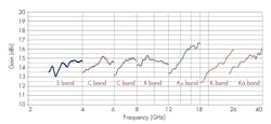
6. The plots show the gain for 3D-printed standard gain horn antennas across a wide range of frequencies.
As was shown for such a wide frequency range, it’s possible to 3D-print a plastic microwave antenna and achieve good performance by applying several coats of conductive paint. One of the keys is in smoothing the active surfaces of the antenna with solvent or mechanical sanding before applying the conductive paint, to achieve the smoothest surface possible. By checking the VSWR of an antenna produced in this manner, it can be verified to have good low-loss performance through microwave frequencies, with performance comparable to that of a solid metal antenna.
Complex antenna shapes can be accommodated by splitting prints into sections that allow for sanding/smoothing access before assembly by gluing or solvent welding. Conductive spray paint easily flows over and covers surface sanding scratches and seams.
Figure 7 compares the gain of a laboratory-grade standard gain horn antenna with 15-dBi gain at S-band frequencies (a model 299 from Waveline) and two copies of a replica produced by means of 3D printing and metallization with two different kinds of conductive paint. The plastic antennas were printed in PLA, solvent-smoothed, and spray-painted with conductive metal paint.
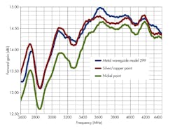
7. These plots compare the gain of two identical 3D-printed standard gain horn antennas using different conductive coatings and a commercial standard gain horn antenna operating across the same frequency range.
All three antennas were tested using the same model 201NF coaxial adapter from Waveline. The gain of the copper/silver-painted 3D-printed antenna was only ±0.2 dB different than that of the commercial horn antenna, well within measurement repeatability. The third curve in Fig. 7 shows the response of the other printed antenna, formed with two coats of nickel-based conductive coating. This conductive coating yields about 0.5 dB less gain than the copper/silver conductive for the identical antenna configuration, degrading by as much as 5 dB to 10 GHz.
For those wishing to experiment with 3D-printed RF/microwave antennas, the STL printable files are available for download. All 3D designs were completed with Sketchup, a free-of-charge n-dimension computer-aided-design (CAD) software tool. The Sketchup files for these horns are also downloadable for those who would like to edit the geometries.
Glenn Robb is Principal Engineer for Antenna Test Lab Co.; Twitter: @antennatestlab. Download files for a 7-horn collection of standard gain horn antennas, as well as STL files for 3D printing, at "Example 11: 3D Printed Antennas."

