CRLH TLs and SIRs Lead to the Incredibly Shrinking Antenna
Download this article as a .PDF
Practical use of realizable circuit structures such as stepped impedance resonators (SIRs) and various forms of transmission lines (TLs) can lead to highly selective, yet also quite small, single- and dual-band antennas. Analysis of antenna designs based on SIRs and composite right/left-handed (CRLH) transmission lines can show how to cover several frequency bands while also miniaturizing the antenna designs, for both quarter-wavelength and half-wavelength antenna configurations.
To demonstrate the approach, quarter- and half-wavelength antennas were designed with a common band centered at 4.5 GHz and an impedance bandwidth (|S11| < −10 dB) of 500 MHz, and with the half-wavelength antenna also handling a second frequency band centered at 1.8 GHz. For a fair comparison of the two configurations, the size of both antennas is the same (26 × 21.3 mm2).
Leveraging Metamaterials
Metamaterials have sparked a great deal of interest among high-frequency designers and researchers in recent years. Metamaterials are characterized by having both negative permittivity and permeability.1,2
Metamaterial structures such as split-ring resonators (SRRs) and complementary SRRs (CSRRs) have been loaded on monopole antennas to effectively reduce the electrical size and increase the number of frequency bands.3-6
Nonresonant and wideband metamaterials have been realized by using a TL that is periodically loaded with series capacitors and shunt inductors, along with conventional TL elements. Such a circuit structure is referred to as a composite right/left-handed (CRLH) TL.7,8 CRLH TLs exhibit a progressive phase shift that can be completely controlled by the loading/parasitic elements’ values in a nonlinear frequency dependence such that both can be used to adjust arbitrary frequency bands.
Several compact single-, dual-, and multi-band antenna designs presented in literature involve use of CRLH TL,9-15 modified versions of CRLH TLs,16-18 and loading monopole/dipole antenna structures with CRLH cells.19-21 Extremely compact antennas have also been employed in multiple-input, multiple-output (MIMO) applications.22,23 However, designing small antennas with simple independent design procedures is an ongoing high-frequency design need that has not been covered completely in the literature.
Impact of Resonance
The performance of many different antennas depends highly on the effect of its resonators or, in general, some form of resonance. These resonant effects are employed in many ways, for example, to form the fundamental operating frequency/band or to provide high isolation for other frequencies. Regardless of the design approach, most antennas face a common challenge, which is the presence of spurious frequencies due to various modes and resonances.
A simple solution is to use filters before or after the antenna block, depending on whether signal information is transmitted or received.24 However, this strategy results in a larger overall structural size. Another solution can be the use of SIRs, which inherently block spurious bands and provide better isolation. Approaches for CRLH-based SIR filters are presented in refs. 25-29. Some attempts for high-selectivity metamaterial-based SIR antennas are also suggested in refs. 30-34.
To show the effectiveness of metamaterials in antenna design, notably the use of SIRs and CRLH transmission lines, λ/4 and λ/2 short-circuited metamaterial SIR transmission lines were explored for application in antenna design as their fundamental element. The λ/4-based antenna has a single-band response at 4.5 GHz while the λ/2-wavelength antenna offers the 4.5-GHz band as well as an additional band at 1.8 GHz for the same geometrical size, with sharper cutoff characteristics.
The antennas are built on low-cost FR-4 substrate material with relative permittivity of 4.3, thickness of 1.6 mm, and loss tangent (tan d) of 0.02. To generate an omnidirectional pattern, the proposed metamaterial SIR antennas were designed in coplanar waveguide (CPW) configurations. The commercial computer-aided-engineering (CAE) circuit design software CST Microwave Studio from Computer Simulation Technology helped in the design process.
The SIR can be realized by cascading transmission lines with different characteristic impedances and electrical lengths. The schematic for quarter-wavelength SIR and half-wavelength SIR are shown in Figs. 1a and 1b, respectively. The term Zi refers to the characteristic impedance, while θi is the electrical length of each transmission line. The resonators can be open or short circuit in configuration. As a result, four possible configurations are available to achieve minimum or maximum impedance. In all configurations, the target resonant condition for employing these structures as antennas requires achieving zero input admittance (Yi = 0).
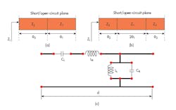
1. The schematic diagrams show a quarter-wave SIR (a) and a half-wave SIR (b), while the equivalent circuit shows a CRLH cell (c).
For a short-circuit, quarter-wavelength SIR antenna, the input impedance can be expressed as Eq. 1:
ZinQ = (jZ2)[(Z2tanθ2 + Z1/tanθ1)/(Z2 – Z1tanθ2/tanθ1)] (1)
The input impedance for a short-circuit lg/2 CRLH SIR can be extracted mathematically by means of Eq. 2:
ZinH = Z2(j[Z2tan(θ2) + Z1tan (2θ1)] + jZ2 tan(θ2)[Z1 – Z2tan(2θ1)tan(θ2)]/Z2[Z1 – Z2tan(2θ1)tan(θ2)] – Z1tan(θ2)[Z2tan(θ2) + Z1tan(2θ1)] ) (2)
The resonant conditions for quarter-wavelength and half-wavelength short-circuit SIR antennas can be achieved when the input impedance is infinite (zero input admittance), as shown by Eqs. 3 and 4:
Z2 = Z1tan(θ2) / tan(θ1) (3)
Z2[Z1 – Z2tan(2θ1)tan(θ2)]
= Z1tan(θ2)[Z2tan(θ2) + Z1tan(2θ1)] (4)
When designing the SIR using CRLH TLs, the parameters expressed as Eqs. 5 and 6 are used for the SIRs:
Zi = {[LLi(ω2LRiCLi – 1)] / [CLi(ω2LLiLRi – 1)]}0.5 (5)
θi = ω(LRiCRi)0.5 {[1 – 1/(ω2CLiLRi)][1 – 1/(ω2CRiLLi)]}0.5 (6)
From Eqs. 5 and 6, and by substitution of Eqs. 3 and 4, it is possible to confirm that the resonant condition has a higher-order degree of freedom for the half-wavelength case compared to the quarter-wavelength case. Thus, more bands and highly selective antennas can be realized using half-wavelength CRLH SIR antenna for short-circuit termination.
Doubling Up
The earlier conclusions can be reinforced through the introduction of two CRLH SIR antennas, a quarter-wavelength and a half-wavelength antenna. Fig. 2 shows a planar 2D layout of the quarter-wavelength antenna. The antenna is formed with two cascaded CRLH cells after the equivalent circuit of Fig. 1c. The first cell is designed using an 11-finger interdigital capacitor and low-value meandered-line inductor. The second cell is realized with a series gap capacitor and high-value meandered-line inductor. Fig. 2 provides details of the antenna’s dimensions. The antenna measures just 26 ´ 21.3 mm2, or only about 30% the size of a conventional patch antenna.
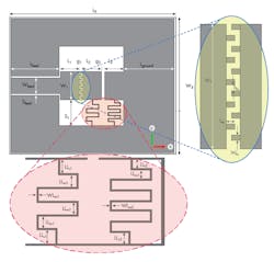
2. This 2D layout shows a CPW short-circuit, half-wavelength (λ/2) CRLH SIR antenna, with Ls = 26 mm; Ws = 21.3 mm; L1 = L2 = L3 = L4 = 3 mm; g1 = g2 = g3 = 0.5 mm; Lfeed = 7.7 mm, Wfeed = 2.5 mm; Sfeed = 0.2 mm; S1 = 4 mm; W1 = 4.6 mm; Lground = 8.1 mm; LL1 = 0.4 mm; LLm2 = 4 mm; LL2=0.65 mm; LLm2 = 0.55 mm; WLm1 = WLm2 = 0.1 mm.
The modification that was added to the quarter-wavelength configuration is to realize the resonator as a half-wavelength configuration (shown earlier in Fig. 1b). The antenna with the modification (as a half-wavelength antennas) is shown in Fig. 3. As can be seen, the antenna consists of three cascaded CRLH TLs. The first and third TLs are identical, with somewhat different TL used between them. The first and third TLs are realized using an interdigital capacitor and low-value meandering-line inductor. The middle TL is realized using an air-gap capacitor. This means that the outer TLs have higher CL and lower LL values, which yields smaller characteristic impedance and nearly equivalent electrical length as can be concluded from Eqs. 5 and 6. In a similar fashion to the short-circuit load, the antenna has a 50-Ω feedline and connected to the short-circuit load. Fig. 2 provides further details of the dimensions for the different components of the antennas.
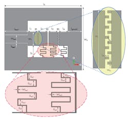
3. This 2D layout shows a CPW short-circuit half-wavelength (λ/2) CRLH SIR antenna with Ls=26 mm; Ws=21.3 mm; L1 = L2 = L3 = L4 = 3 mm; g1= g2 = g3 = 0.5 mm; Lfeed= 7.7 mm; Wfeed = 2.5 mm, Sfeed = 0.2 mm; S1 = 4 mm; W1 = 4.6 mm; Lground = 4.6 mm; LL1=0.4 mm; LLm2= 0.5 = 4 mm; LL2 = 0.65 mm; LLm2 = 0.55 mm; WLm1 = WLm2 = 0.1 mm.
The simulated reflection coefficients of the proposed antennas (quarter- and half-wavelength SIR antennas) are shown in Fig. 3. It can be clearly seen that the lg/4 quarter-wavelength antenna has a single resonance at 4.6 GHz for which the reflection coefficient is −20 dB with an impedance bandwidth (|S11| < −10 dB) of 0.6 GHz (from 4.4 to 5 GHz).
The half-wavelength CRLH SIR antenna has two resonances, at 1.8 and 4.5 GHz. At both frequencies, the reflection coefficient is closer to −15 dB. However, the first band is very selective (a sharper cutoff) at 1.8 GHz, whereas the second band has a comparatively flatter slope. The proposed half-wavelength antenna design is only 5% and 29% the size of two separate conventional patch antennas used to handle 1.8 and 4.5 GHz separately.
What About the Radiation?
The radiation properties of the quarter-wavelength CRLH SIR antenna were investigated by plotting the simulated three-dimensional (3D) gain radiation pattern at 4.6 GHz (Fig. 4). The quarter-wavelength SIR antenna has a typical omnidirectional pattern with a realized gain of 2.169 dB and good radiation efficiency of 77.5% (Fig. 5). The maximum radiation directivity occurs along the Z-direction (the broadside of the antenna geometry) and has null radiation along the C direction (the feeding direction).
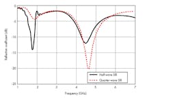
4. A commercial simulation program produced this simulated reflection coefficients for the quarter- and half-wave SIR antennas.
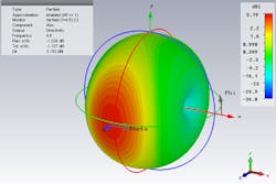
5. This simulation shows the 3D directive gain radiation pattern at 4.6 GHz.
The simulated 3D radiation patterns of the half-wavelength CRLH SIR antenna are plotted in Figs. 6a and 6b for the two resonant frequencies at 1.8 and 4.6 GHz, respectively. The half-wavelength antenna design exhibits similar high-directivity properties at both frequencies, in the manner of the quarter-wavelength antenna at its single frequency. The maximum directivity occurs in the broadside direction (Z-direction). The antenna has different radiation efficiencies at the two frequencies: 72% at 4.5 GHz and 1% at 1.8 GHz. The low efficiency at the lower frequency (1.8 GHz) can be attributed to the small physical size of the antenna for that wavelength.
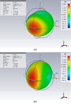
6. This simulation shows the 3D directive gain radiation pattern at 1.8 GHz (a) and 4.5 GHz (b).
Small antennas can be designed using CRLH SIR technology, as has been shown for two different configurations. These two antennas are quarter-wavelength and half-wavelength CRLH SIR antennas with only one cell, each a fraction the size of a conventional printed antenna. In the case of the half-wavelength antenna, the proposed design approach can result in antennas as small as only 5% the size of a conventional printed antenna.
Department of Electronic Engineering, Military Technical College, Cairo, Egypt
Department of Computer and Electrical Engineering, University of Waterloo, Waterloo, Canada
Student Member, IEEE
School of Electrical Engineering, University of Manchester, Manchester, UK
References
- Nader Engheta, and Richard W. Ziolkowski, Eds., Metamaterials: Physics and Engineering Explorations, Wiley, New York, 2006.
- Ricardo Marqués, Ferran Martín, and Mario Sorolla, Metamaterials with Negative Parameters: Theory, Design, and Microwave Applications, Vol. 183, Wiley, New York, 2011.
- Meng Li, Xian Qi Lin, Jessie Yao Chin, Ruopeng Liu, and Tie Jun Cui, “A Novel Miniaturized Printed Planar Antenna Using Split-Ring Resonator,” IEEE Antennas and Wireless Propagation Letters, Vol. 7, 2008, pp. 629-631.
- Li-Ming Si, Weiren Zhu, and Hou-Jun Sun, “A Compact, Planar, and CPW-Fed Metamaterial-Inspired Dual-Band Antenna,” IEEE Antennas and Wireless Propagation Letters, Vol. 12, 2013, pp. 305-308.
- S. K. Sharma and R. K. Chaudhary, “Dual-band Metamaterial-inspired Antenna for Mobile Applications,” Microwave and Optical Technology Letters, Vol. 57, No. 6, 2015, pp. 1444-1447.
- Walaa Wahba, Mahmoud Abdalla, Ahmed Mohamed, and Abdelmegeed Allam, “A Uni-Planar Microstrip CSRR metamaterial Antenna,” 2014 IEEE AP-S International Antenna and Propagation Symposium Digest, Memphis, TN, July 6-11, 2014, pp.545-546.
- C. Caloz and T. Itoh, Electromagnetic Metamaterials Transmission Line Theory and Microwave Applications, Wiley, Paramus, NJ, 2006.
- G. V. Eleftheriades and K. G. Balmain, Negative Refractive Metamaterials, Wiley, Paramus, NJ, 2005.
- Cheng-Jung Lee, Wei Huang, A. Gummalla, and M. Achour, “Small Antennas based on CRLH Structures: Concept, Design, and Applications,” IEEE Antennas and Propagation Magazine, Vol. 53, No. 2, 2011, pp. 10-25.
- R. W. Ziolkowski, P. Jin, and C. Lin, “Metamaterial-Inspired Engineering of Antennas,” IEEE Proceedings, Vol. 99, No. 10, 2011, pp. 1720-1731.
- M. Abdalla and Z. Hu, “Compact and Tunable Metamaterial Antenna for Multi-band Wireless Communication applications,” 2011 IEEE AP-S International Antenna and Propagation Symposium Digest, July 2011, pp. 2951-2953.
- S. K. Sharma, and R.K. Chaudhary, “A Compact Zeroth-order Resonating Wideband Antenna with Dual-band Characteristics,” IEEE Antennas and Wireless Propagation Letters, Vol. 14, 2015, pp.1670-1672.
- Mahmoud A. Abdalla, Walaa W. Wahba, and Abdelmegid M. Allam, “Asymmetric dual-band integrated compact CRLH SIW array antenna,” Journal of Electromagnetic Waves and Applications, Vol. 31, No. 3, 2017, pp. 284-296.
- Li, Long, Zhen Jia, Feifei Huo, and Weiqiang Han, “A novel compact multiband antenna employing dual-band CRLH-TL for smart mobile phone application,” IEEE Antennas and Wireless Propagation Letters, Vol. 12, 2013, pp. 1688-1691.
- Jeong Keun Ji, Gi Ho Kim, and Won Mo Seong, “Bandwidth enhancement of metamaterial antennas based on composite right/left-handed transmission line,” IEEE Antennas and Wireless Propagation Letters, Vol. 9, 2010, pp. 36-39.
- Mahmoud A. Abdalla and Mohamed I. Abdelnaser, “A Compact Dual Band D-CRLH Antenna with Radiation Pattern Directional Characteristics,” 2016 IEEE AP-S International Antenna and Propagation Symposium Digest, 2016, Portorreco, pp. 277-278.
- Mohammad Bemani, Saeid Nikmehr, and Mahdi Fozi, “A Dual-Band Feed Network for Series-Fed Antenna Arrays Using Extended Composite Right/Left-Handed Transmission Lines,” IEEE Transactions on Antennas and Propagation, Vol. 65, No. 1, 2017, pp. 178-189.
- M. A. Abdalla and Z. Hu, “A Compact Dual Band Meta-material Antenna for Wireless Applications,” 2012 Loughborough Antennas & Propagation Conference, Loughborough, UK, pp. 1-4, 2012.
- J. Zhu and G.V. Eleftheriades, “Dual-band metamaterial-inspired small monopole antenna for WiFi applications,” Electronics Letters, Vol. 45, No. 22, 2009, pp. 1104-1106.
- M. A. Abdalla, U. Abdelnaby, and A. A. Mitkees, “Compact and Triple Band Meta-material Antenna for All WiMAX Applications,” 2012 International Symposium on Antennas and Propagation (ISAP), 2012, pp. 1176 – 1179.
- S. Jamilan, M. A. Antoniades, J. Nourinia, and M. N. Azarmanesh, “A compact multiband printed dipole antenna loaded with two unequal parallel NRI-TL metamaterial unit cells,” IEEE Transactions on Antennas and Propagation, Vol. 63, No. 9, 2015, pp. 4244-4250.
- Ahmed A. Ibrahim and Mahmoud A. Abdalla, “CRLH MIMO Antenna with Reversal Configuration,” AEÜ- International Journal of Electronics and Communications, Vol. 70, No. 7, pp. 1134-1141,2016.
- Mahmoud A. Abdalla and Ahmed A. Ibrahim, “Design and Performance Evaluation of Metamaterial Inspired MIMO Antennas for Wireless Applications,” Wireless Personal Communication, 2016, pp. 1-17.
- C. A. Balanis, Antenna Theory and Design, Wiley, Paramus, NJ, 2005.
- S. Karimian, M. A. Abdalla, and Z. Hu, “Left-handed Stepped Impedance Resonator for WLAN Applications,” 2009 3rd International Congress on Advanced Electromagnetic Material in Microwave and Optics, London, UK, August 30 to September 4, 2009, pp. 1-4.
- S. Karimian, M. Abdalla, and Z. Hu, “Compact Half-wavelength Metamaterial Stepped Impedance Resonator (SIR),” 2011 IEEE AP-S International Antenna and Propagation Symposium Digest, July 3-8, 2011, Spokane, WA, pp. 1054-1057.
- S. Karimian, M. Abdalla, and Z. Hu, “Tunable Metamaterial Ferrite Stepped Impedance Resonator (SIR),” 2010 PIERS, 27th Progress in Electromagnetics Research Symposium, March 2010, Xi'an, China, pp 165-168.
- Paris Vélez, Miguel Durán-Sindreu, Armando Fernández-Prieto, Jordi Bonache, Francisco Medina, and Ferran Martın, “A Compact Dual-Band Differential Power Splitter With Common-Mode Suppression and Filtering Capability Based on Differential-Mode Composite Right/Left-Handed Transmission-Line Metamaterials,” IEEE Antennas and Wireless Propagation Letters, Vol. 13, 2014, pp. 536-539.
- Mahmoud A. Abdalla and Ahmed A. Ibrahim, “Metamaterials Sculpt UWB Bandpass Filter,” Microwaves and RF, Vol. 56, No. 3, March 2017, pp. 1-4.
- Mahmoud. A. Abdalla, Aliaa A. Awad, and Khaled M. Hassan, “Wide Band High Selective Compact Metamaterial Antenna for 2 GHz Wireless Applications,” 2014 Loughborough Antennas & Propagation Conference, November 10-11, 2014, Loughborough, UK, pp. 350-354.
- M. A. Abdalla, S. Karimian, and Z. Hu, “Dual Band Spurious-Free SIR Metamaterial Antenna,” 2014 IEEE AP-S International Antenna and Propagation Symposium Digest, July 2014, pp. 1005-1006.
- Mahmoud Abdalla, Mohamed Abo El-Dahab, and Mohamed GHouz, “SIR Double Periodic CRLH Loaded Dipole Antenna,” 2015 IEEE AP-S International Antenna and Propagation Symposium Digest, July 2015, Vancouver, Canada, pp. 832-833.
- Y. Kushiyama, T. Arima, and T. Uno, “Differential-Type CRLH Leaky-Wave Antenna Using Stepped Impedance Resonators,” IEEE Antennas and Wireless Propagation Letters, Vol. 15, 2016, pp. 321-324.
- S. K. Sharma, M. A. Abdalla, and R. K. Chaudhary, “An Electrically Small SICRR Metamaterial‐inspired Dual‐band Antenna for WLAN and WiMAX applications,” Microwave and Optical Technology Letters, Vol. 59, No. 3, 2017, pp. 573-578.

